The cuk converter is dc to dc converter gives an output voltage which is less than or greater than the input voltage with a polarity reversal. That means, the polarity of output voltage is opposite to that of the input voltage. Figure 1 shows the cuk converter using BJT.

Circuit diagram & Working of Cuk Converter
Initially when the input voltage Vs is applied and the transistor T is in the off state, the capacitor C1 charges through L1 and Dm. to a voltage equal to Vs. The equivalent circuit of this mode is shown in Fig. 2. The circuit operation can be divided into two modes.
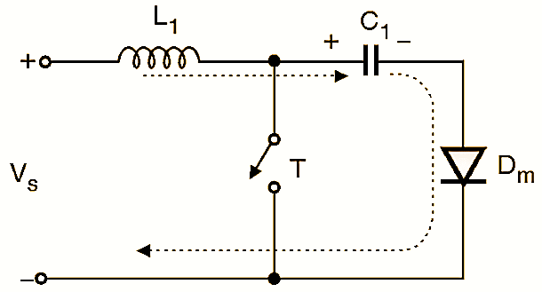
Figure 2.
Mode 1 (0 to t1 ):
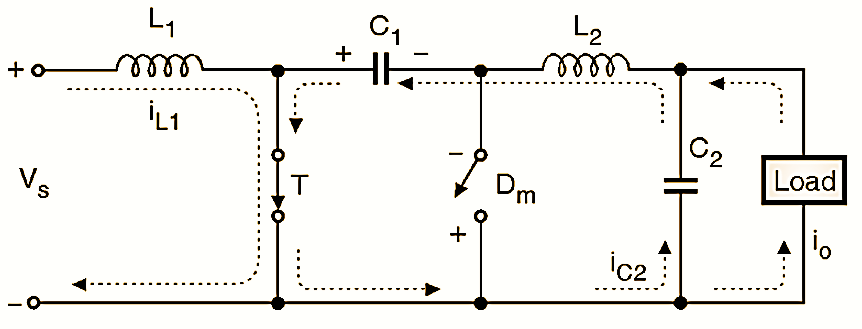
Figure 3: Equivalent Circuit Diagram for mode I (Cuk Converter).
At t = 0, transistor T is turned ON and it starts acting as a closed switch. So current through L1 starts increasing. The voltage across C1 gets applied across Dm to reverse bias it, and turns it off. The equivalent circuit of this mode is shown in Fig. 3. The inductor L1 continues to store energy. Capacitor C1 will discharge its energy through the circuit formed by C1, C2, load and L2, as shown in Fig. 3. Mode 1 comes to an end at t = t1 and the circuit enters into mode 2.
Mode 2 (t1 to t2):
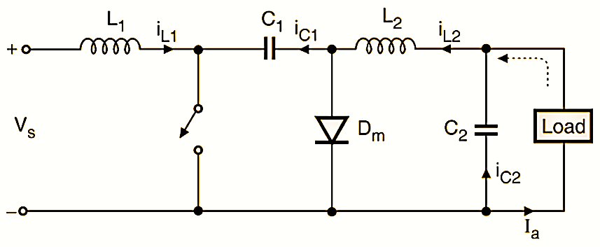
Figure 4: Equivalent Circuit Diagram for mode II (Cuk Converter).
At t = t1 the transistor T is turned off. Capacitor C1 is charged from the input supply and the energy stored in L2 is transferred to the load. The diode Dm and transistor T provide a synchronous switching action. C1 acts as a medium to transfer energy from source to load. Fig. 4 shows the equivalent circuit for mode 2.
Waveforms of Cuk Converter
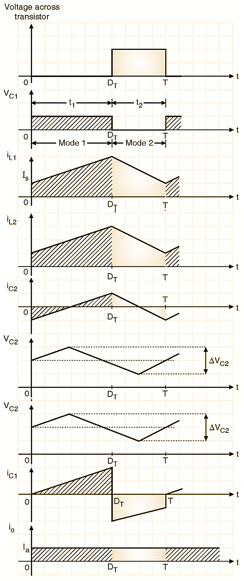
Figure 5: Waveforms of Cuk Converter.
Various voltage and current waveforms when the circuit reaches its steady state are shown in Fig. 5 assuming the load current to be continuous.
Advantages of Cuk Converter
Some of the major advantages of the Cuk converter are as follows :
- The cuk converter operation is based on the transfer of capacitor energy. Hence the input current is continuous.
- This circuit has low switching losses.
- It has a high efficiency.
Disadvantages of Cuk Converter
Some of the major disadvantages of the Cuk converter are as follows :
- A high value peak current flows through the transistor.
- Ripple current of the capacitor C1 is high.
- This circuit requires an additional capacitor and an inductor.
Features of Cuk Converter
Some of the important features of the Cuk converter are as follows :
- It can provide an output voltage which less that or greater than the input voltage.
- Its input current is constant and it has low switching looses.
- It has high efficiency.