A boost converter set up the output voltage is more (i.e., stepped up) than the DC input voltage. Hence, this converter is called boost converter.
Working Principle of Boost Converter
The line voltage on rectification gives unregulated D.C voltage, which fluctuates due to the changes in magnitude of the line voltage. This unregulated D.C voltage is given as input to the boost converter to obtain the required controlled DC output voltage. This required control is obtained by varying the duty cycle from 0 to 1 which varies the output voltage, Eo from Ed.c to ∞ which is a stepped up output voltage.
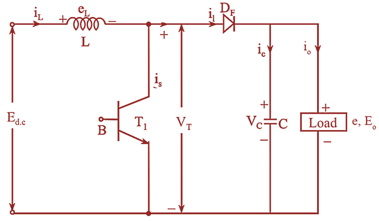
Figure 1: Circuit Diagram of Boost Converter.
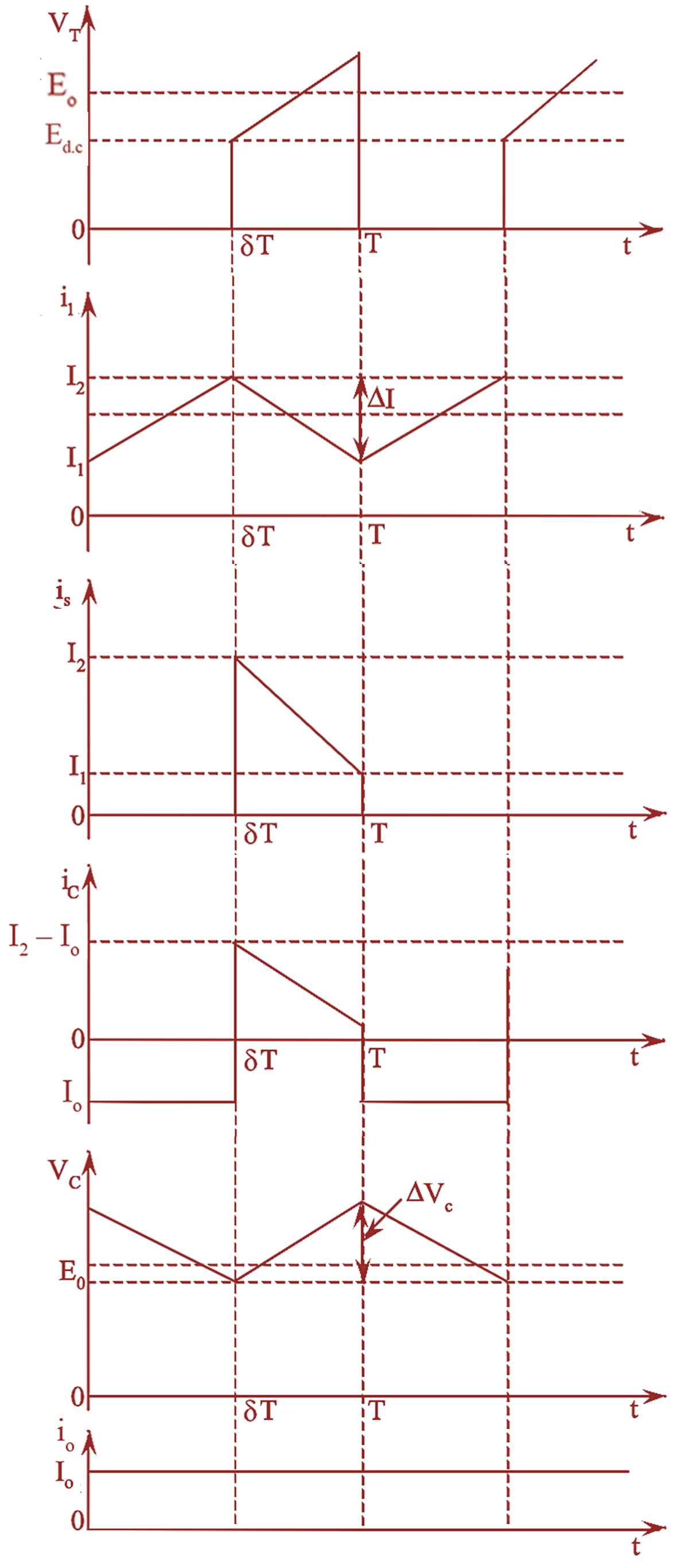
Figure 2: Waveforms of Boost Converter.
Figure (1) shows the circuit setup of boost converter and figure (2) depicts the voltage and current waveforms for a continuous inductor current. The operation of the boost converter can be explained in two modes.
Mode 1
At t = 0, power transistor is turned ON.
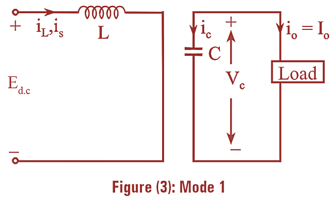
The rising input current flows through the inductor L and the transistor Tl. The inductor connected to the supply Ed.c, stores energy during this period. Thus from the circuit diagram of figure (1) it can be seen that the diode DF would be reverse biased thus isolating the output stage. The equivalent circuit for mode 1 is as shown in figure (3).
Mode 2
At t = TON, Transistor is switched OFF
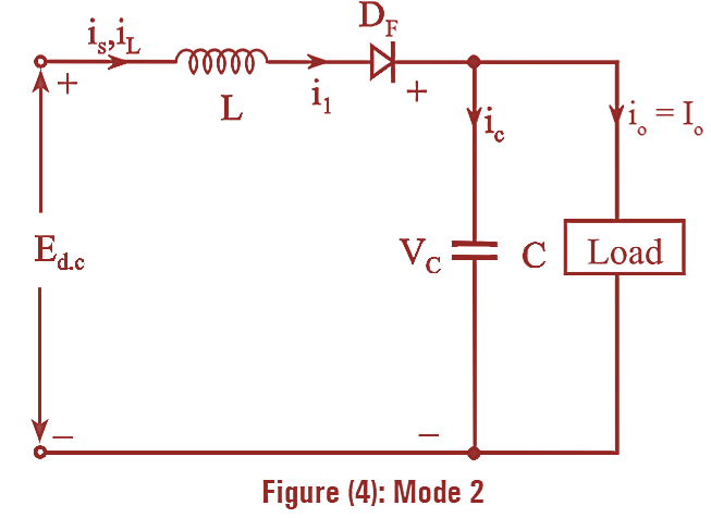
During this period the current flows through L – Df – C — load. The energy stored in the inductor, L is transferred to the output stage and the current in the inductor reduces till the transistor is turned ON in the next cycle. The equivalent circuit for the operation of mode 2 is as shown in figure (4).
Derivation for Boost Converter
Assuming a linear rise in the inductor current from I1 to I2, we get,
\[{{E}_{d.c}}=L\left( \frac{{{I}_{2}}-{{I}_{1}}}{{{T}_{ON}}} \right)\]
\[{{E}_{d.c}}=L\frac{\Delta I}{{{T}_{ON}}}…(1)\]
\[{{T}_{ON}}=L\frac{\Delta I}{{{E}_{d.c}}}…(2)\]
Also, assuming a linear fall in the inductor current at t = TOFF from I2 to I1, we get
\[{{E}_{d.c}}-{{E}_{o}}=-L\frac{{{I}_{2}}-{{I}_{1}}}{{{T}_{OFF}}}\]
\[{{E}_{d.c}}-{{E}_{o}}=-L\frac{\Delta I}{{{T}_{OFF}}}…(3)\]
\[{{T}_{OFF}}=L\frac{\Delta I}{\left( {{E}_{o}}-{{E}_{d.c}} \right)}…(4)\]
Where, ΔI = (I2 – I1) is the peak-to-peak ripple current of the inductor L.
Now, from equation (2) and equation (4) the peak-to- peak ripple current of the inductor L is obtained as,
\[\Delta I={{E}_{d.c}}\frac{{{T}_{ON}}}{L}=\left( {{E}_{o}}-{{E}_{d.c}} \right)\frac{{{T}_{OFF}}}{L}…(5)\]
Substituting TON = δT and TOFF = (l – δ) T, we get,
Average output voltage,
\[{{E}_{o}}={{E}_{d.c}}\frac{T}{{{T}_{off}}}=\frac{{{E}_{d.c}}T}{\left( 1-\delta \right)}\]
\[=\frac{{{E}_{d.c}}}{\left( 1-\delta \right)}\]
By interchanging equation (6), we get,
Voltage gain,
\[\frac{{{E}_{o}}}{{{E}_{d.c}}}=\frac{1}{\left( 1-\delta \right)}\]
Advantages of Boost Converter
- A boost converter can step-up the output voltage without a transformer
- The circuitry of boost converter requires only one transistor (switch) and hence its efficiency is high.
Disadvantages of Boost Converter
- High peak current flows through the power transistor.
- Stabilizing the regulator may be difficult as the output voltage is very sensitive to changes in duty cycle.
- Require large filter capacitor and large inductors.
Applications of Boost Converter
- A boost converter finds its application in regulated D.C power supplies.
- It is used in the regenerative braking of D.C motors.