A TCR is a thyristor controlled inductor, connected in shunt with the line, in which the thyristor valve is controlled by partial conduction, in order to continuously vary the effective reactance of the line. TCR is a Variable impedance type static VAR generator, in which the reactor current can be varied by applying the firing delay angle control method.
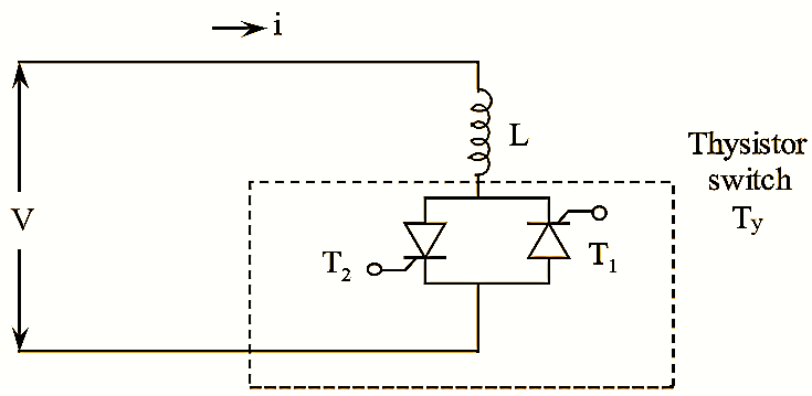
Figure 1: Thyristor Controlled Reactor (TCR).
Working Principle and Waveforms of Thyristor Controlled Reactor (TCR)
A basic TCR is shown in figure (1). It consists of two main components, thyristor switch (Ty) and linear reactor ‘L’. Thyristor switch comprises of two back to back thyristors which conduct on alternate half cycles of the supply frequency. If a gate pulse is applied to the thyristors, it results in conduction of thyristor valve or switch. The current in the reactor can be controlled from maximum to zero value by varying the firing delay angle α.
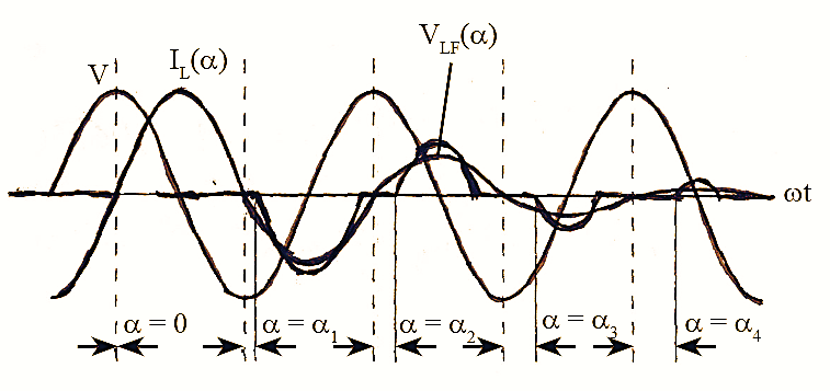
Figure 2: Waveforms of Thyristor Controlled Reactor (TCR)
The duration of current conduction intervals is controlled by delaying the closure of the thyristor switch with respect to the peak applied voltage once in each half cycle as shown in figure (2).
When α = 0°. the thyristor switch (Ty) gets closed at the peak of the applied voltage, the amplitude is maximum and hence the resulting current in the reactor is equal to the steady state current. When α = 90°. the amplitude is zero and hence there is no current flow during the corresponding half cycle. The TCR current as a function of angle, (a) can be expressed as,
\[{{I}_{LF}}(\alpha )=\frac{V}{\omega L}\left( 1-\frac{2\alpha }{\pi }-\frac{\sin 2\alpha }{\pi } \right)\]
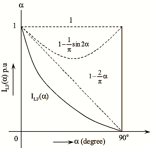
Figure 3.
Where.
V – Amplitude of applied voltage
L – Inductance of TCR
ω – Angular frequency of applied voltage.
The amplitude variation of the fundamental TCR current with the delay angle a is shown in figure (3). From figure (3), it can be observed that the TCR can control the current continuously from zero to a maximum value.
Characteristics of Thyristor Controlled Reactor (TCR)
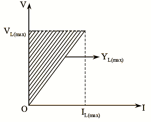
Figure 4: V-I Characteristics of Thyristor Controlled Reactor (TCR)..
The TCR ratings are decided as per the operational requirement. It can be operated in specified V-I region. The boundaries of this region is determined by maximum voltage, current and admittance which are shown in figure (4).
Where,
VL(max) – Maximum voltage
IL(max) – Maximum current
YL(max) – Maximum admittance
If TCR operates at fixed delay angle, α = 0° (say), then it act as Thyristor Switched Reactor(TSR). When TSR is fed from A.C supply it gives fixed inductive admittance and its reactive current is directly proportional to the supply voltage.