Earth Tester generally used for measurement of earth resistance.
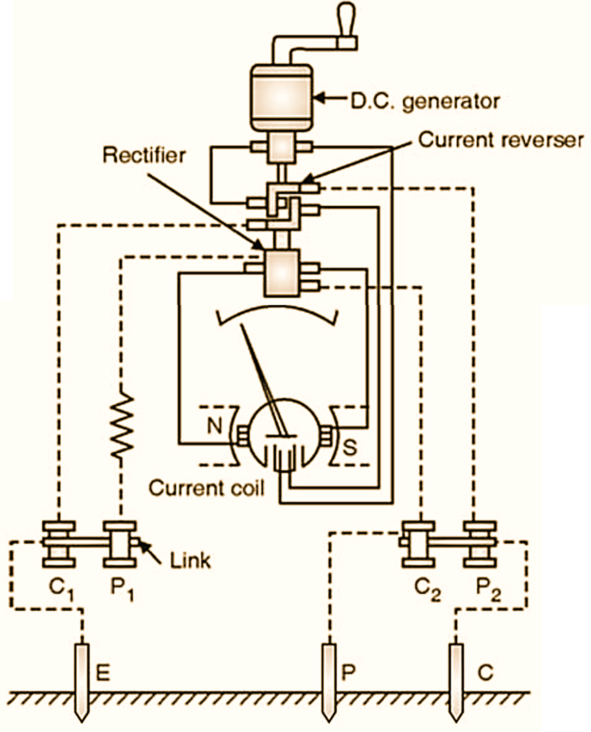
Figure 1: Earth Tester.
Construction of Earth Tester
The constructional details of which are shown in Fig. 1. Earth Tester consists of a hand cranked type generator; the magnet poles, crossed coils and flexible spirals. It consists of a rotating current converter and a rectifier in addition to a ohm-meter. Both of these consist of simple commutator made up of ‘L’ shaped segments, mounted on the shaft of the generator and rotated at the same speed by the operating handle, each commutator has four fixed brushes in contact with it.
One pair of each set is so positioned that they make contact alternately with one segment and them with other, as the armature rotates.
The second pair of each set of brushes is positioned on the commutator, so that continuous contact is made with one segment, whatever the position of the commutator.
Considering the action of the ‘current reverser’ a unidirectional voltage is applied to the first pair of brushes from the generator so that as the shaft rotates each segment of the commutator makes alternate connections, first with the positive and then with the negative brush; the voltage on the segments thus reverses, giving an alternating voltage, as the commutator rotates which will appear across the second pair of brushes. In this way alternating voltage is produced across the terminals C1 and C2.
With the rectifier commutator the action is reverse of the above, the alternating voltage across P1, P2 being turned into a direct voltage which is then applied to the movement of the instrument. Since both commutator rotate at the same speed, the converting and rectifying actions are in step, i.e. they synchronize.
Working Principle of Earth Tester
It is connected to the earth whose resistance is to be measured and the other spikes P and C when handle is rotated (Generator), the direct current flows from the generator through the current coil of the movement to the current reverser, and alternating current from the reverser through the soil between the electrodes E and C. The alternating voltage drop between the electrodes P and E is rectified, by the rectifier and fed to the potential coil of the meter. As the indication of the meter depends upon the ratio of the potential across its potential coil, and current passing through its current coil; the deflection of its pointer will indicates directly the resistance in ohms of the earth under test.
Measurement Procedure Using Earth Tester
For measuring the earth resistance, the current electrode ‘C’ must be driven into the soil at a sufficient from the earth plate E. Also the potential electrode P must be driven in at a point which is outside the resistance area of both E and C. As a rough guide, the current electrode should be 25 m to 30 m away and potential electrode about half the distance from E. Take three readings of earth resistance with the potential electrode at different positions in turn;
- Midway between E and C,
- 3 m nearer E,
- 3 m nearer C.
If the three readings agree substantially, take the mean of these as correct value of earth resistance.