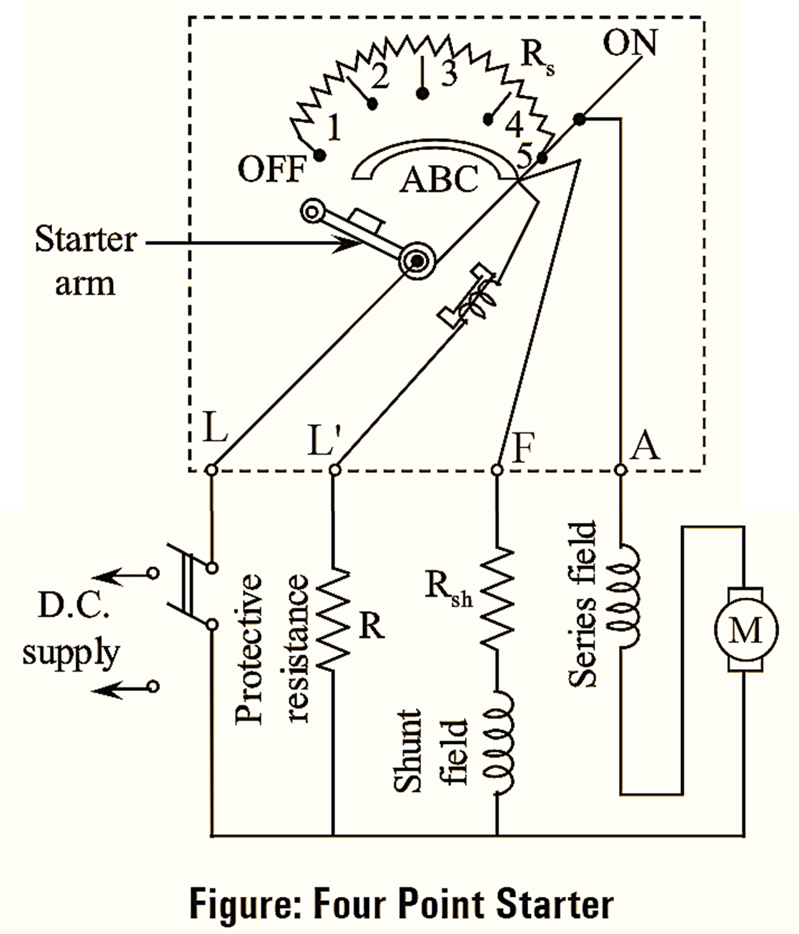
A four point starter is a protective device used in shunt and compound DC motors to limit the high starting current in the absence of back e.m.f. The construction of four point starter is similar to three point starter except the connection of NVC (No-volt coil). The N-V coil connected in series with field winding in three point starter is replaced in four point starter by connecting it across the supply through an additional terminal, N as shown in figure. In this type of arrangement, when the armature touches stud number 1, the line current divides into three parts. In which, first part passes through starting resistance, series field and armature. The second part passes through shunt field winding and the third part passes through N-V coil and protective resistance.
In four-point starter since N-V coil current is independent of shunt field circuit current, any change of current in shunt field does not affect the current passing through the N-V coil. Thus, the electromagnetic pull exerted by the N-V coil will always be sufficient to hold the handle in RUN position under all the operating conditions and prevents the spiral spring from resisting the starting arm to OFF position. The function of No-volt release and overload release in four point starter is similar to three point starter.
Difference between 3 -point and 4-point starters.
|
3-point Starters |
4-point Starters |
| The name 3-point starters is given because it has three terminals (L,F,A) available from the starters. | The name 4-point starters is given because it has four terminals (L,L,F,A) available from the starters. |
| They are used when no (or little) speed control is required. | They are used when no (or little) speed controls wide range of speed. |
| It consists of two parallel circuits, one consisting of over load release, starting resistances and armature and the other includes no volt release, rheostat and shunt field winding. | 4-point starter consists of three parallel circuits, one consisting of overload release, starting resistances and armature, the second consists of a variable resistance and shunt field winding and the third includes a holding coil. |
| During normal operations for low field currents, the holding magnet releases the starter arms which is undesirable. | Change in the field current (for the variation of speed of motor) does not affect the current drawn by the holding coil. |
| They are not suitable for motors working with controlled motors. | They are suitable for motors working with speed controlled motors. |