The constructional details of a three point starter are shown in Fig. 1. This is called as a three point starter because three points L, A and F are brought out for the external connections.
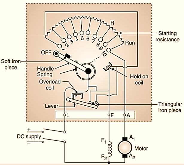
Point L: It is the line terminal and should be connected to the positive terminal of the dc supply.
Point A: It is to be connected to the armature winding.
Point F: It is to be connected to the field winding.
Point L is connected to the overload coil the second end of which is connected to the handle of the starter. We can move this handle from OFF to RUN positions manually. The spring attached to the handle can bring the handle back to its original position i.e. OFF position. This starter is basically a variable resistor which is divided into a number of sections (ten in Fig. 1). The contact points 1,. 2, …. 10 are called as studs. The handle makes contact with these studs when it is moved from points 1 to 10 or in the other direction.
Construction of a three point starter
A connection is made from stud 1 to the hold on coil or no volt coil as shown in Fig. 1. The other end of no volt coil is connected to the terminal F. The Overload Coil (OLC) and No Volt Coil (NVC) are the additional protections provided in the three point starter.
Operation of three point starter
The sequence of operation is as follows:
Initially the handle is in the “OFF” position and the DC supply is turned on. The handle is then moved slowly to make contact with stud 1. As soon as it makes contact with stud 1, the dc supply gets connected directly to the field winding through the hold on coil as shown in Fig. 2(a). The rated field starts flowing and rated flux is produced. The dc supply gets connected to the armature winding as well but via the complete starter resistance as shown in Fig. 2(b). So a small armature current starts flowing. Thus the armature current at the time of starting is kept below a safe value.
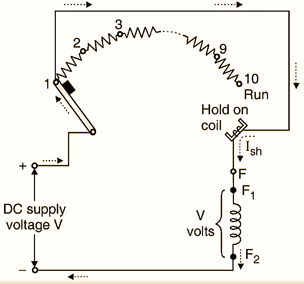
(a) The dc supply gets connected across the field winding when handle makes contact with stud 1.
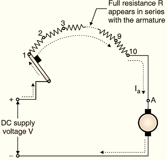
(b) DC supply gets connected to the armature through the full starter resistance.
Fig. 2
Now the handle is moved further towards the “RUN” position, slowly. The starter resistance coming in series with the armature is gradually cut-out as we move the handle from OFF to RUN position. The armature current increases gradually and motor gradually accelerates. When the starter handle reaches the RUN position, the entire starter resistance is cutout and the motor starts running at the normal speed, as shown in Fig. 2.32.2(c).
Function of NVC or Hold on Coil
Now let us see the operation of the NVC or hold on coil. The field current flows through the hold on coil and it starts acting as an electromagnet. So when the handle is moved manually to the RUN position, the soft iron piece on the handle experiences a force of attraction as shown in Fig. 2.32.2(c). Thus once the handle reaches the RUN position, it remains there due to the magnetic force of attraction produced by the hold on coil. Whenever the supply fails, the current flowing through the NVC goes to zero. So it loses its electromagnetic properties and the handle returns back to the OFF position under the influence of the spring. This will switch off the motor. So when the supply is applied again, the whole starter resistance appears in series with the armature and we have lo start the motor again by using the starter as explained earlier. Thus the entire starter resistance appears in series with the armature every time when an attempt is made to start it. If the supply voltage goes below a particular level then the current through NVC will be very small and it will lose its electromagnetism. This will release the handle and the handle will return to the OFF position.
Function of the Overload Coil
Let us now discuss the function of the overload coil. The overload coil is an electromagnet. The motor current is taken through this coil.
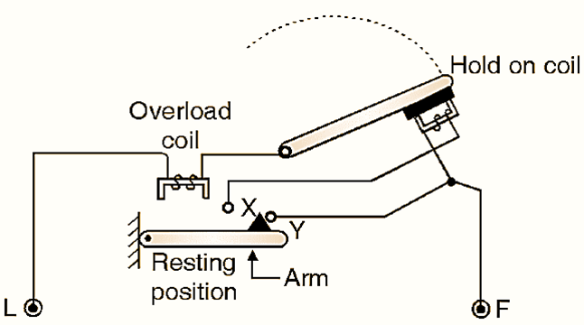
Operation under normal condition
Refer Fig. 2.32.3(a) which shows the equivalent circuit under Operation under normal condition. Below the overload coil there is an arm which is fixed at its fulcrum and it is resting in the horizontal position under the normal condition as shown in Fig. 2.32.3(a).
(a) Under normal operation condition.
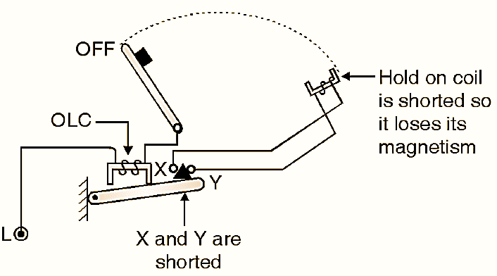
(b) When overloading lakes place.
Fig. 3 : Function of overload coil
Operation when the overloading takes place:
When the motor current crosses a predetermined limit. the overload condition is said to have occurred. The current flowing through the overload coil will produce a force of attraction, which will lift the arm upwards as shown in Fig. 2.32.3(b). This will lift the triangular iron piece and the points X and Y are connected to each other through it as shown in Fig. 2.32.3(b). As points X and Y are shorted. the hold on coil is short circuited, the voltage across it reduces to zero. The hold on coil will lose its magnetic properties and the handle is returned back to the off state. Thus the motor is saved if it draws an excessive current from the source.
Disadvantage of 3 point starter:
The hold on coil and the field winding are connected in series with each other in the 3-point starter. So if we reduce the field current to exercise the flux control. tlieii the current flowing through the hold on coil will also reduce. If this current goes below a certain level, then the force of attraction produced by the hold on coil will be insufficient to hold the handle in the RUN position and so the handle will return back to the OFF position. The motor will be switched off. This disadvantage can be overcome by using the four point starter.