Variable reluctance stepper motor employs the principle of minimum reluctance path i.e. the magnetic circuit gets completed by the flux taking the minimum reluctance path, just as in electric circuit, the current takes the minimum resistance path. Depending on the stator excitations the motor aligns itself so as to provide a minimum reluctance path for the flux.
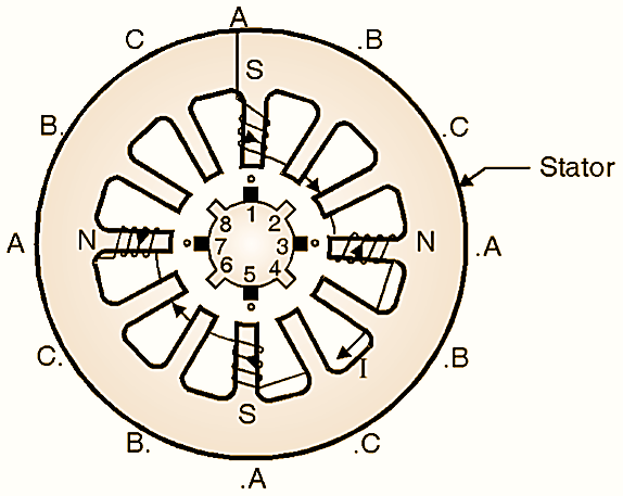
Fig. 1: Variable Reluctance Stepper Motor.
As an illustration consider a simplified version of a single stack, three phase variable reluctance motor with 12 teeth on stator, 4 teeth per phase which can be excited and an unexcited rotor with 8 teeth. Each phase consists of four stator teeth and the windings on them are connected in series with each other as shown in Fig. 1. The rotor is made up of a ferromagnetic material which has very high magnetic permeability. Each phase consists of four stator teeth and the windings on them are connected in series with each other as shown in Fig. 1. The rotor is made up of a ferromagnetic material which has very high magnetic permeability. At a time only one phase is excited by allowing a dc current to flow through it. The sequence in which the phases are switched, will decide the direction of rotation of the rotor.
Working of Variable Reluctance Stepper Motor
As shown in Fig. 2(a) when phase A of the stator winding is excited the rotor aligns itself such that four of the rotor teeth are in perfect alignment with four of the phase A stator teeth so as to provide a minimum reluctance path. (Rotor teeth numbers 1, 3, 5 and 7 are aligned), as shown in Fig. 2(a).
(a) Rotor teeth in perfect alignment with the stator teeth.
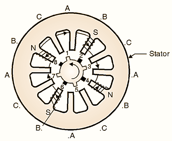
(b) Phase B excited
Fig. 2: Variable Reluctance Stepper Motor
Next if phase B of stator is excited as shown in Fig. 2(b) the rotor aligns itself such that four rotor teeth (2, 4, 6 and 8) which were closest to four phase B stator teeth are in perfect alignment with four phase B stator teeth to provide a minimum reluctance path for the flux (See Fig. 2 (b)). This causes the rotor to rotate in the anticlockwise direction by an angle of 15 degrees which is the difference of the rotor and stator tooth pitches. Thus if we continue the excitation in the phase sequence A, B, C, A, B, C, A we have the rotor rotating in the anticlockwise direction in steps of 15 degrees.
Clockwise rotation:
Now after phase A if phase C instead of phase B is excited as shown in Fig. 1.17.1(c) then the rotor aligns itself such that four rotor teeth which were closest to then four phase C stator teeth, get perfectly aligned to them. This causes the rotor shaft to rotate in the clockwise direction by an angle again equal to the difference of the stator and rotor tooth pitches i.e. 15 degrees.
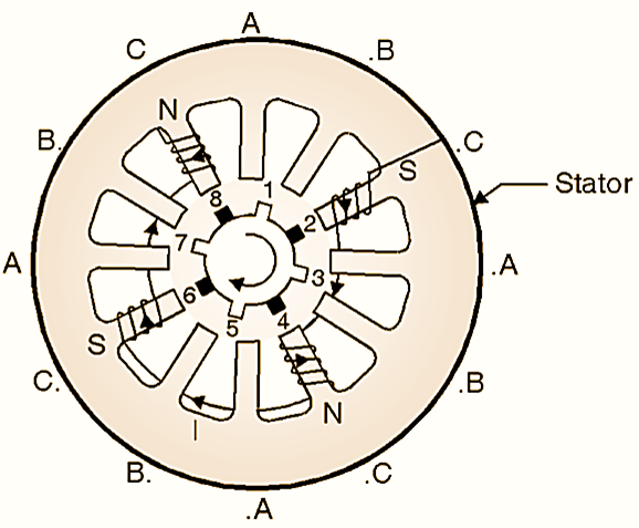
Thus if we continue the excitation in the phase sequence A, C, B, A, C, B, A,…. we have the rotor rotating in the clockwise direction with steps of 15 degrees. For the excitation sequence of A-B-C-A, three changes of excitations shown in Figs. 1.17.1(a), (b) and (e) result in rotor movement by one rotor tooth pitch. The rotor tooth pitch is equal to (360/p) degrees where p is the number of rotor teeth. Since all the step angles are equal, the step angle of the three phase motor in Fig. 1.17.1 is (360/3×8) = 15°. In general for a “m” phase motor with p rotor teeth.
Step angle = degrees …(l.17.l)
The motor described above is single stack variable reluctance motor. There are multiple stack variable reluctance stepper motors that operate on the same principle.