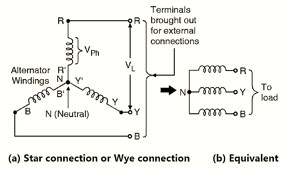
Figure 1.
Star Connection (Y Connection) is obtained by connecting one end of the three phase windings together.
Connection diagram :
The star or Wye connection of the three alternator windings is shown in Fig. 1(a). We can connect either R Y B or R’ Y’ B’ together. This common point is called as the Neutral Point and it is denoted by N. The remaining three ends of the windings are brought out for the external connections. These ends are denoted by R-Y-B as shown in Fig. 1(b).
A 3-Phase Star Connected Supply :
Line voltage definition :
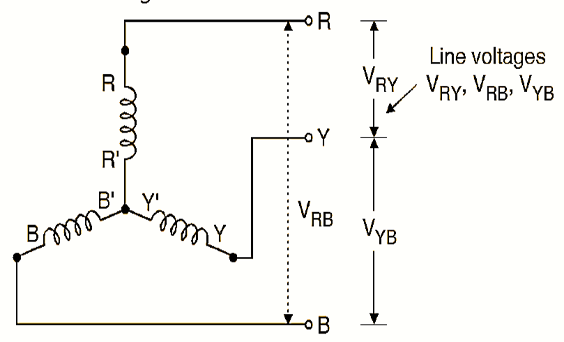
Figure 2. Line Voltages for star connection.
If R, Y and B are the supply lines, then the potential difference between any two lines is known as the line voltage VRY, VRB, VYB, VYR, VBR and VBY are six possible line voltages as shown in Fig. 2. All the line voltages are sinewaves of 50 Hz frequency and the phase shift between the adjacent line voltages is 60°. Refer Fig. 2 to understand the concept of line voltages for a star connected load.
Phase voltage definition :
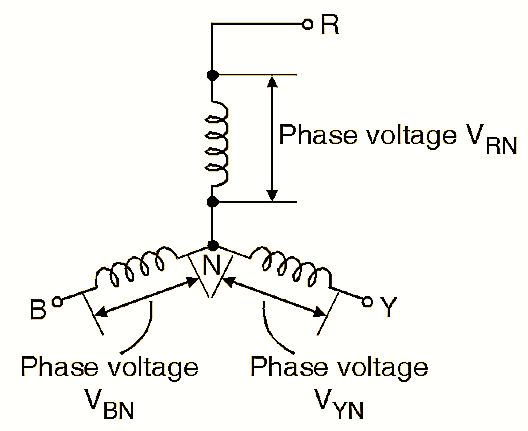
Figure 3. Phase Voltages for star connection.
A phase voltage is defined as the voltage measured across a single winding or phase. The phase voltages are thus the voltages measured with respect to neutral. VRN, VYN, and VBN are three possible line voltages as shown in Fig. 3. All the phase voltages are sine waves of 50 Hz frequency and the phase shift between the adjacent line voltages is 120°. In the star connected systems the line voltages and phase voltages are of different values.
Note: The definitions of phase voltage and line voltage are general definitions and they are applicable to the star connection as well as the delta connection.
Typical values of line and phase voltages :
Typically, the RMS phase voltage is 230 or 240 V. Whereas the RMS line voltage is 415 V or 440 V and the frequency of phase and line voltages is 50 Hz. Thus in the star connected system the line voltage is higher than the phase voltage by a factor \(\sqrt{3}\text{ }\).
\[\text{Line voltage = }\sqrt{3}\text{ phase voltage }\]
and
\[\text{Phase voltage = }\frac{\text{Line voltage }}{\sqrt{3}}\]
Relation between Phase and Line Current :
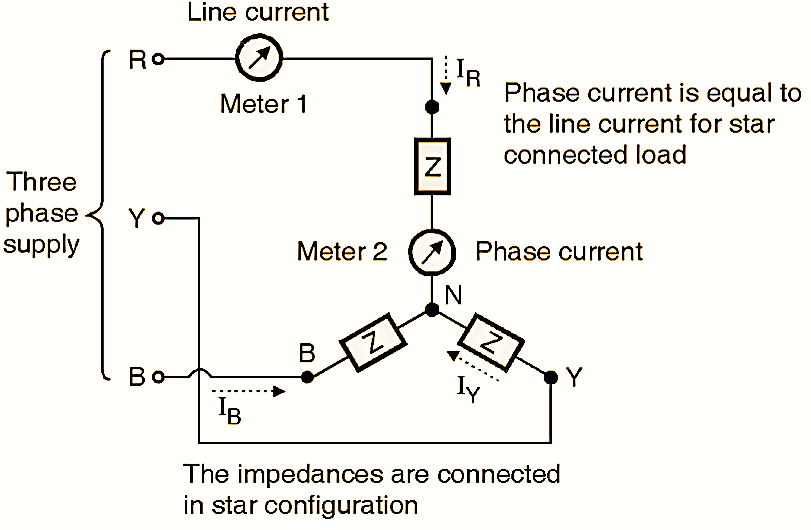
Figure 4. Line current and phase current for star connected load.
The current passing through any branch of the star connected load is called as the phase current. IR, IY and IB are the phase currents. Meter 2 in Fig. 4 measures the phase current IR.
\[{{\text{I}}_{\text{ph}}}\text{ = }{{\text{I}}_{\text{R}}}\text{ = }{{\text{I}}_{\text{Y}}}\text{ = }{{\text{I}}_{\text{B}}}\]
Line current definition:
The current passing through any line R, Y, B is called as the line current. As shown in Fig. 4, meter-1 measures the line current IR. The line current in general is denoted by IL. IR, IY and IB are the line currents. Fig. 4 measures the line current IR.
\[{{\text{I}}_{\text{L}}}\text{ = }{{\text{I}}_{\text{R}}}\text{ = }{{\text{I}}_{\text{Y}}}\text{ = }{{\text{I}}_{\text{B}}}\]
Relation between Iph and IL :
As the current flowing through each line is equal to the current flowing through the corresponding branch, the line current is equal to the phase current. For star connected load IL = Iph.
Summary of current and voltage relations :
Relations between voltages and currents for the star connected load have been shown in Fig. 5.
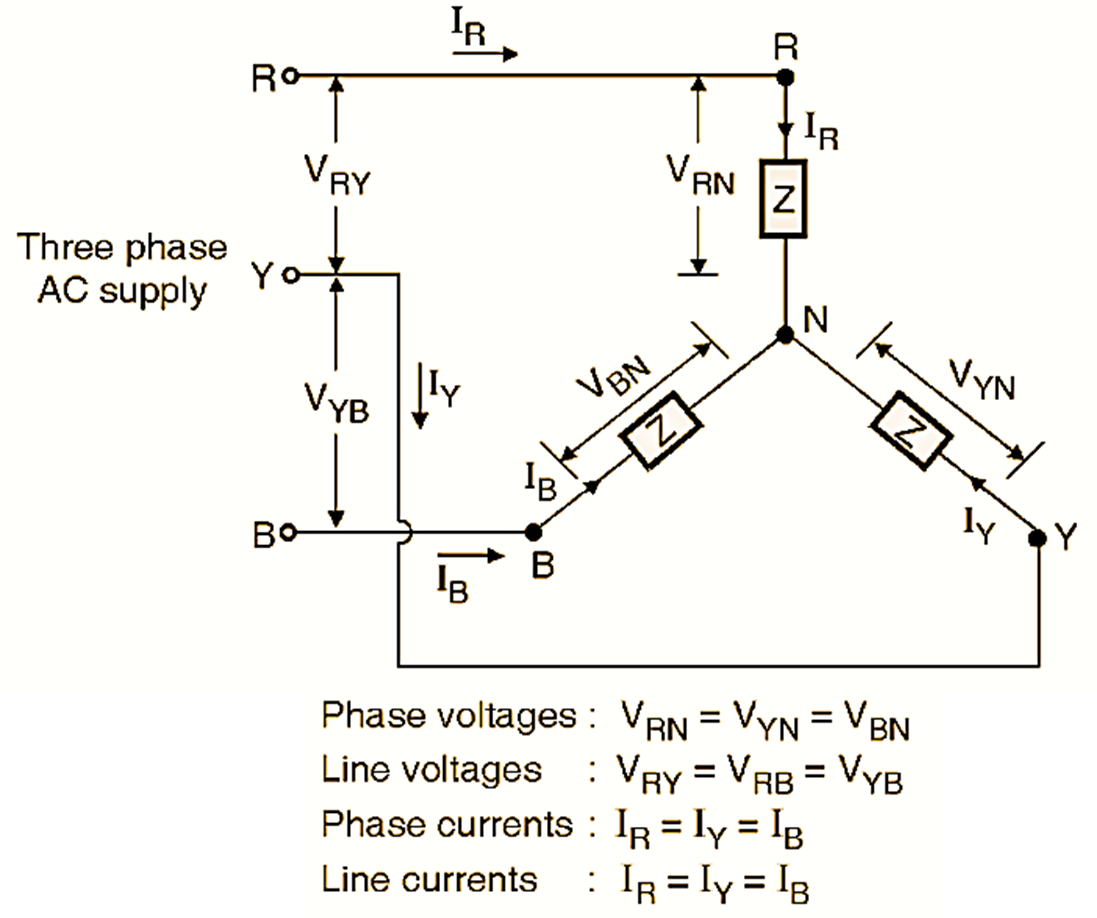
Figure 5. Relationship between currents and voltages for star connected load.
Relations between Line and Phase voltages
Derivation :
To obtain the relation between the phase voltage Vph and the line voltage VL, let us consider the line voltage. Referring to Fig. 5 we can express VRY as,
\[{{\overline{V}}_{RY}}={{\overline{V}}_{RN}}+{{\overline{V}}_{NY}}\]
The bar indicates vector addition.
But,
\[{{\overline{V}}_{NY}}=-{{\overline{V}}_{YN}}\]
\[{{\overline{V}}_{RY}}={{\overline{V}}_{RN}}-{{\overline{V}}_{YN}}\]
Instead of writing, \({{\overline{V}}_{RN}}\) or \({{\overline{V}}_{YN}}\) we can write VR and VY for simplicity.
\[{{\overline{V}}_{RY}}={{\overline{V}}_{R}}-{{\overline{V}}_{Y}}\]
Similarly, the other line voltages can be expressed as,
\[{{\overline{V}}_{YB}}={{\overline{V}}_{Y}}+{{\overline{V}}_{B}}\]
\[{{\overline{V}}_{BR}}={{\overline{V}}_{B}}-{{\overline{V}}_{R}}\]
The line voltage is \(\sqrt{3}\) times higher than the phase voltage and leads VR by 30°. This is graphically shown in Fig. 6. It is possible to obtain the values of line voltages VYB and VBR in a similar way.
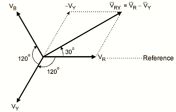
Figure 6. Plotting VRY graphically.
Note :
For a star connected load, the magnitude of line is voltage is \(\sqrt{3}\) times higher than that of a phase voltage,
\[{{V}_{L}}=\sqrt{3}{{V}_{ph}}\]
Complete Phasor Diagram
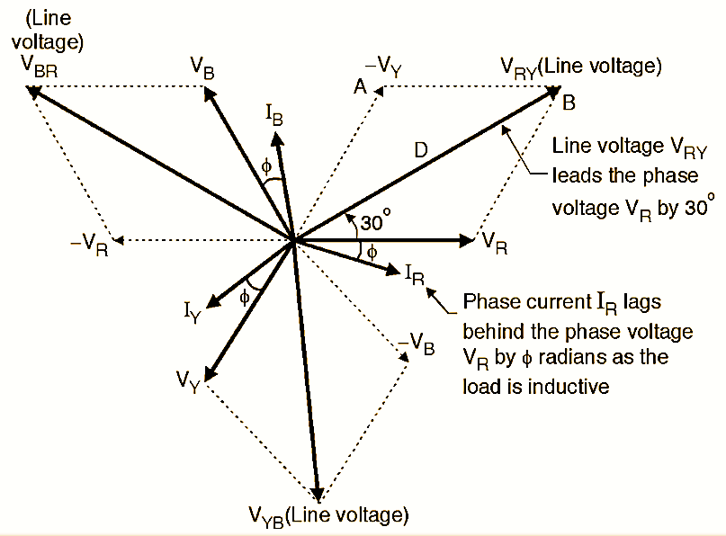
Figure 7. Complete phasor diagram of star connected balanced load.
Now let us draw the phasor diagram which includes all the phase voltages, line voltages and currents. Depending on the nature of load (resistive, inductive or capacitive) the current will be in phase, lagging or leading with respect to the corresponding voltages.
The phase voltage and phase current are related to each other as follows :
\[\left| Z \right|=\frac{\left| {{V}_{ph}} \right|}{\left| {{I}_{ph}} \right|}\]
\[\left| {{I}_{ph}} \right|=\frac{\left| {{V}_{ph}} \right|}{\left| Z \right|}\]
Fig. 7 shows the complete phasor diagram for a 3 phase star connected load for lagging power factor (R + L type load).
Conclusions from the phasor diagram :
- Phase currents IR, IY and IB lag behind the corresponding phase voltages VR, VY and VB by radians respectively as the load is inductive.
- The line voltages VRY, VBR and VYB are displaced by 120º from each other.
- The line voltages lead their respective phase voltages by 30º. So VRY leads VR, VBR lead VB and VYB lead VY by 30º.