Plugging is the simplest type of braking which involves re-connection of motor to supply in such a way that motor develops torque in opposite direction to the movement of rotor system, speed will decrease till zero speed is reached where mechanical brakes are applied and then it will accelerate in opposite direction. This method is also called reverse voltage braking or counter current braking. This method requires special device to disconnect the supply as soon as system comes to rest. This method is used to get either a quick reversal or to get a rapid stop. This type of braking can be applied to,
- DC motors
- Induction motors
- Synchronous motors.
Plugging Braking of DC Motor
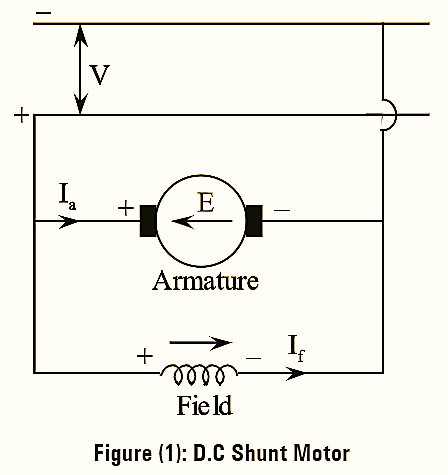
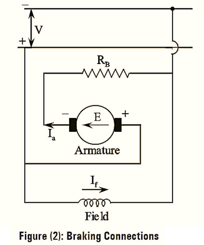
In order to under- stand the concept of plugging, consider a D.C shunt motor running with a constant speed, N as shown in figure (1). The polarities of the armature and the field can be observed under running condition as shown in figure (1). Under running operation, the back e.m.f of the motor E is nearly equal to the supply voltage V and acts in the opposite direction. Now, to perform the braking operation by plugging, consider the connection diagram of the same shunt motor as shown in figure (2). It can be observed in figure (2) that during the braking operation the polarities of the armature are reversed with the polarities of field unchanged. Thus, a reverse voltage appears across the armature. This causes the induced armature voltage (back emf) E to act along the direction of the supply voltage V. Hence. E no longer opposes V and as a result voltage aiding a large reverse current flows through the armature. This reverse current would be of twice the magnitude that of normal current, as twice the supply voltage (i.e., V + E ≅ 2V) is impressed on the armature having low resistance.
A large reverse current leads to a large negative torque (braking torque). In case of starting the motor during plugging operation also, it is necessary to limit the reverse current. The limitation of reverse current limits the reverse torque and thus reduces the stress on the motor. This is achieved by inserting an additional resistor called the braking resistor RB in series with the armature during plugging. Current at the instant of braking,
\[{{I}_{a}}=\frac{V+E}{{{R}_{B}}}….(1)\]
Electric braking torque,
\[{{T}_{b}}=\frac{\text{Braking Power}}{n}\]
\[{{T}_{b}}=\frac{{{P}_{B}}}{n}\]
\[=\frac{\left[ E_{a}^{2}/{{R}_{B}} \right]}{n}\]
\[{{T}_{b}}={{k}_{1}}\phi \left[ \frac{V+{{k}_{2}}N\phi }{{{R}_{B}}} \right]\text{ }\left[ E={{k}_{2}}N\phi \right]\]
\[=\frac{{{(n{{k}_{a}})}^{2}}}{{{R}_{B}}n}\]
\[=\frac{nk_{a}^{2}}{{{R}_{B}}}\]
The instant when the motor attains zero speed after the braking operation, the supply must be disconnected. This is done because the motor starts rotating in the reverse direction.
Thus, plugging has two modes. They are,
- Plug to stop
- Plug to reverse.
If plugging is required only for stopping the motor, then the supply has to be switched OFF at zero speed. This mode represents the ‘plug to stop’ mode. If the supply is continued, then the motor operates in the reverse direction and the mode is called plug to reverse mode.
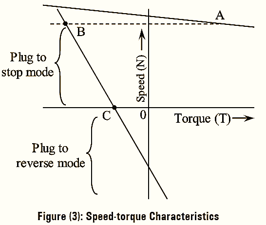
The speed-torque characteristics of the shunt motor during plugging are shown in figure (3).