A current transformer (CT) is nothing but a coil wound on a toroidal core. When a large current carried by a conductor is to be measured, it is advisable to avoid the direct connection of ammeter in this high current circuit. For this purpose a current transformer is used.
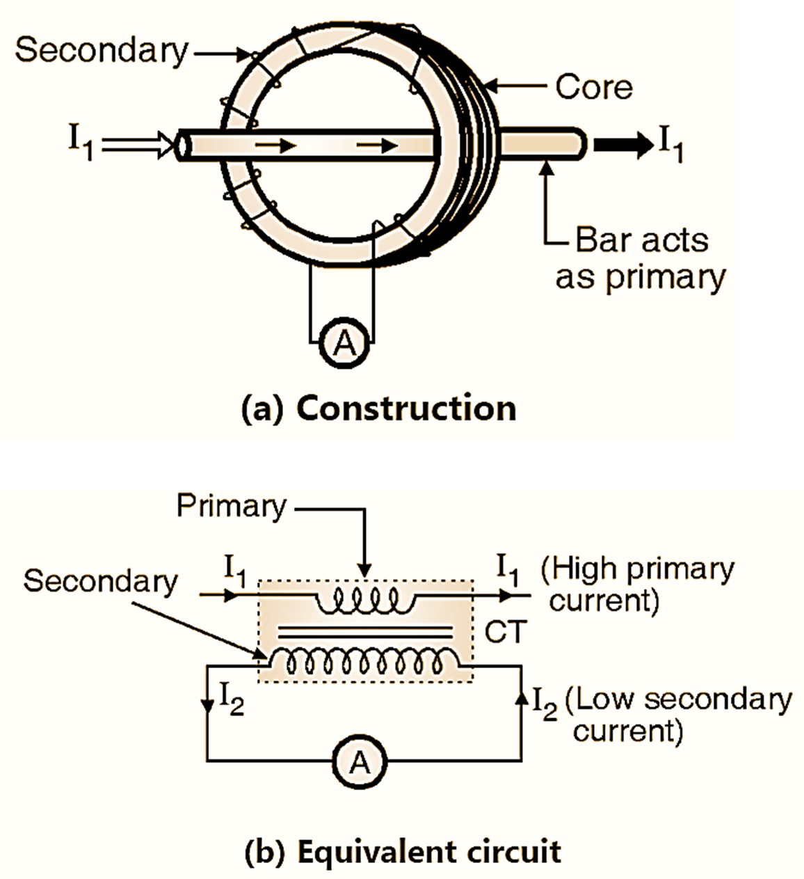
Fig. 1 : Connection of Current Transformer (CT) to measure current.
A Current Transformer (CT) is a type of transformer used in power systems to measure alternating current (AC) by stepping down high current levels to a safer and manageable level for instruments such as ammeters, protection relays, or energy meters. This makes it easier to measure, monitor, and control the electrical system without directly dealing with high current.
We have to take an important precaution while operating with a CT. The precaution is that the CT should never be operated with its secondary open circuited. The secondary should be either shorted or a small when it is not connected to the meter resistance should be connected across it. If the secondary is open circuited, then the secondary ampere turns will become zero. These secondary ampere turns generally oppose the primary turns. So as the secondary ampere turns become zero, this opposition is reduced to zero and the primary ampere turns (mmf) will produce a large flux in the core. The excessive flux has two effects on the operation. First effect is increase in core loss resulting in core heating beyond safe limits. The second effect is that a large emf is induced on the primary and secondary sides, which can damage the insulation of windings. The excessive secondary induced voltage is dangerous for the user as well. Hence operation of a CT with open circuited secondary should always be avoided. The secondary of CT is generally connected to ground to protect the user against the possible shocks.
Connection Diagram of Current Transformer (CT)
The construction of a current transformer is shown in Fig. 1 (a) and its equivalent circuit is shown in Fig. 1 (b). CT has a primary coil which is of one or more turns. In Fig. 1 (a), the bar acts as the primary. The primary of CT carries the large current I1 which is to be measured, so the bar is of large cross sectional area. The secondary of a CT is made up of large number of turns. It is wound on a core. The secondary winding is a low current winding hence its cross sectional area is small. An ammeter of small range (typically 0-5 A) is connected across the secondary shown as Fig. 1 (b).
Working Principle of Current Transformer (CT)
CT is basically a step up transformer. Hence the secondary is a high voltage low current winding. The current is stepped down. The secondary current is given by,
\[{{I}_{2}}={{I}_{1}}\times \frac{{{N}_{1}}}{{{N}_{2}}}\]
Where,
N2 >> N1
The current I2 is measured by the ammeter. So if we know the turns ratio N1 / N2 then it is possible to measure I1 (i.e. the large current). The ammeter can be calibrated directly to measure the current I1, if the turns ratio is known. Thus a CT can be used to measure a high current without actually connecting the ammeter directly in series with the high current.
\[{{I}_{1}}=\frac{{{N}_{1}}}{{{N}_{2}}}\times {{I}_{2}}\]
Advantages of Current Transformer (CT)
Some of the advantages of a CT are as follows :
- It is possible to use the ammeters of normal current range to measure very high currents.
- We can calibrate the same ammeter to measure different currents by adjusting the turns ratio of the CT
- The user is safe due to the isolation provided by the current transformer between high current primary and low current secondary.
- The CT can be used to operate indicating and protecting devices such as relays.
- The same CT can be used to provide the measured current to several instruments.
Disadvantages of Current Transformer (CT)
- It can be used to measure only the ac current. The DC current cannot be measured.
- CT cannot be operated with open circuited secondary.
Uses of a Current Transformer (CT)
Current Transformers (CTs) are widely used in electrical systems for a variety of purposes. Below are the main uses:
- CTs are used to measure high currents in power systems by stepping them down to manageable levels that can be safely measured by standard instruments like ammeters, energy meters, and power analyzers. This allows accurate current monitoring without exposing the measuring instruments to high currents.
- Overcurrent Protection: CTs supply input to protective relays, which detect abnormal current conditions (e.g., short circuits, overcurrents) and trigger circuit breakers to isolate the fault.
- Earth Fault Protection: CTs detect ground faults by comparing current imbalances between conductors.
- Differential Protection: CTs are used in transformers, generators, and motors to detect internal faults by comparing the current entering and leaving a system.
- CTs step down high currents for energy meters in industrial, commercial, and residential setups to measure power consumption accurately. They are essential for billing in systems with high voltage and current.
- Used in power systems to monitor load conditions, enabling early detection of overloads or potential failures. Provides data for load analysis, capacity planning, and predictive maintenance.
- CTs electrically isolate the high-voltage, high-current primary circuit from the low-voltage, low-current secondary circuit, ensuring safety for instruments and operators.
- CTs are used in systems like differential protection schemes to detect discrepancies between currents at different points in a circuit. For example, in transformers, differential CTs compare input and output currents to detect internal faults.
- CTs are used in feeder and transmission line protection to detect fault currents and initiate breaker operations.
- CTs provide input to automatic control systems for managing load sharing, synchronizing generators, and regulating voltage and current.
- CTs are used with power factor meters to measure the reactive power in a system, enabling correction of the power factor by adding capacitors or inductors.
- CTs are used in laboratories and testing facilities to calibrate equipment by generating a proportional and manageable test current.
Applications of Current Transformer (CT)
- Substations: For protection and metering in high-voltage systems.
- Industries: For process monitoring, energy management, and equipment protection.
- Commercial Buildings: For load monitoring and energy billing.
- Generator Protection: Detect faults and ensure safe operation.
- Motors and Transformers: For overload and fault detection.