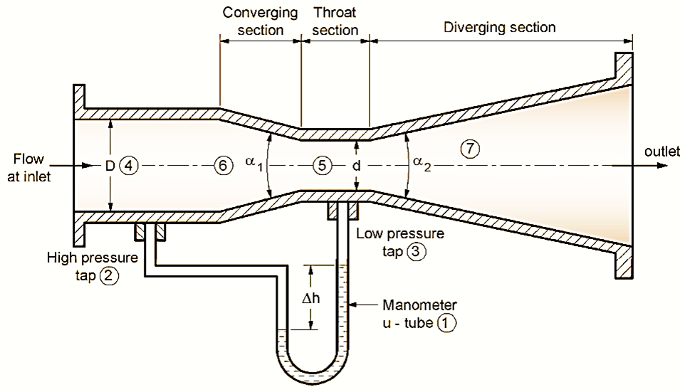
Figure 1: Venturimeter.
A venturimeter is a device used to measure the flow rate of a fluid (liquid or gas) through a pipe. It is based on the principle of Bernoulli’s equation, which relates the pressure, velocity, and elevation of a fluid in steady flow.
Working Principle of Venturimeter
The venturimeter operates on the principle of the Venturi effect, which states that when a fluid flows through a constricted section of a pipe, its velocity increases while the pressure decreases. By measuring the pressure difference between the wider section and the constricted throat, the flow rate can be determined.
Main Parts of Venturimeter
- U-tube manometer
- High pressure tap
- Low pressure tap
- Diameter at inlet section (D)
- Diameter at throat section (d)
- α1 inclined angle (19 to 23°)
- α2 inclined angIe (5° to 15°)
Construction of Venturimeter
- Inlet Section:
- A large-diameter section where the fluid enters.
- It is connected to a high-pressure tap for pressure measurement.
- Converging Section:
- A gradually tapering section reduces the pipe diameter.
- This accelerates the fluid, increasing its velocity and lowering the pressure.
- Throat Section:
- The narrowest section where the fluid velocity is at its maximum, and the pressure is at its minimum.
- A low-pressure tap is placed here.
- Diverging Section:
- A gradually expanding section that slows down the fluid, recovering some of the pressure.
- Ensures the flow returns to normal conditions downstream.
- Pressure Taps:
- High-pressure and low-pressure taps connected to a U-tube manometer.
- Measures the pressure difference (Δ between the inlet and throat.
Working of Venturimeter
Fluid enters the venturimeter through the inlet, where the pressure is measured using the high-pressure tap. As the fluid passes through the converging section, its velocity increases, and the pressure decreases due to the reduced cross-sectional area. At the throat, the velocity is at its maximum, and the pressure is at its minimum. The low-pressure tap measures the pressure at this point. The U-tube manometer measures the pressure difference between the inlet and the throat. The height difference (Δ) in the manometer corresponds to the pressure difference. The fluid slows down as it flows through the diverging section, recovering some pressure while avoiding flow separation.
Liquid flow route
Flow comes from pipe of diameter ‘D’ and introduces inside, then passed through throat of less diameter ‘d’ then comes in the diverging section of inclination of angle α2.
Location of pressure taps from where the manometer tube is introduced – One tap at inlet section and second at middle of throat section. This arrangement provided to measure the pressure difference (P1 – P2) by manometer u-tube.
Derivation of Flow Rate for a Venturimeter
The derivation involves applying Bernoulli’s equation and the continuity equation.
From Bernoulli’s Equation
\[P_1 + \frac{1}{2} \rho v_1^2 = P_2 + \frac{1}{2} \rho v_2^2\]
Rearranging to find the pressure difference:
\[P_1 – P_2 = \frac{1}{2} \rho \left( v_2^2 – v_1^2 \right)\]
The continuity equation is:
\[A_1 v_1 = A_2 v_2\]
From this, the velocity at the inlet (\(v_1\)) is expressed as:
\[v_1 = \frac{A_2}{A_1} v_2\]
Substituting \(v_1 = \frac{A_2}{A_1} v_2\) into the Bernoulli’s equation for pressure difference
\[P_1 – P_2 = \frac{1}{2} \rho \left( v_2^2 – \left( \frac{A_2}{A_1} v_2 \right)^2 \right)\]
Also
\[P_1 – P_2 = \frac{1}{2} \rho v_2^2 \left( 1 – \left( \frac{A_2}{A_1} \right)^2 \right)\]
The pressure difference (\(\Delta P\)) is
\[\Delta P = P_1 – P_2 = \frac{1}{2} \rho v_2^2 \left( 1 – \left( \frac{A_2}{A_1} \right)^2 \right)\]
Rearranging for \(v_2\)
\[v_2 = \sqrt{\frac{2 \Delta P}{\rho \left( 1 – \left( \frac{A_2}{A_1} \right)^2 \right)}}\]
The volumetric flow rate (\(Q\)) is
\[Q = A_2 v_2\]
Substitute \(v_2\)
\[Q = A_2 \sqrt{\frac{2 \Delta P}{\rho \left( 1 – \left( \frac{A_2}{A_1} \right)^2 \right)}}\]
The final flow rate equation is
\[Q = A_2 \sqrt{\frac{2 \Delta P}{\rho \left( 1 – \left( \frac{A_2}{A_1} \right)^2 \right)}}\]
where,
: Cross-sectional areas of the inlet and throat.
Δ: Pressure difference.
: Fluid density.
Advantages of Venturimeter
- Accurate measurement of flow rate.
- Low energy loss compared to orifice meters.
- Suitable for large-diameter pipes.
- Good characteristics.
- Suitable for flow of suspended fluids.
- More accurate.
- Low permanent loss.
- Suitable for high flow rate.
- No tear or wear as surface is smooth.
Disadvantages of Venturimeter
- Large size so occupies more space.
- Higher cost.
- Not easy for inspection.
- It cannot be used for small pipe diameters.
Applications of Venturimeter
- Used in water supply systems, oil pipelines, and chemical industries.
- For measurements, liquids, slurries, dirty fluids etc.
Features of Venturimeter
- The main venturi tube is of cast iron or steel.
- Flow coefficients = 0.984.
- Accuracy much more ± 0.25 to ± 3%.
- Sizes 100 mm to 813 mm.