No-load Test
No-load Test is conducted on the 3-phase induction motor to determine no-load current I0, no-load power factor windage and friction losses, no-load copper loss (I02R), no-load power input P0, no-load resistance R0 and magnetizing reactance X0 etc.
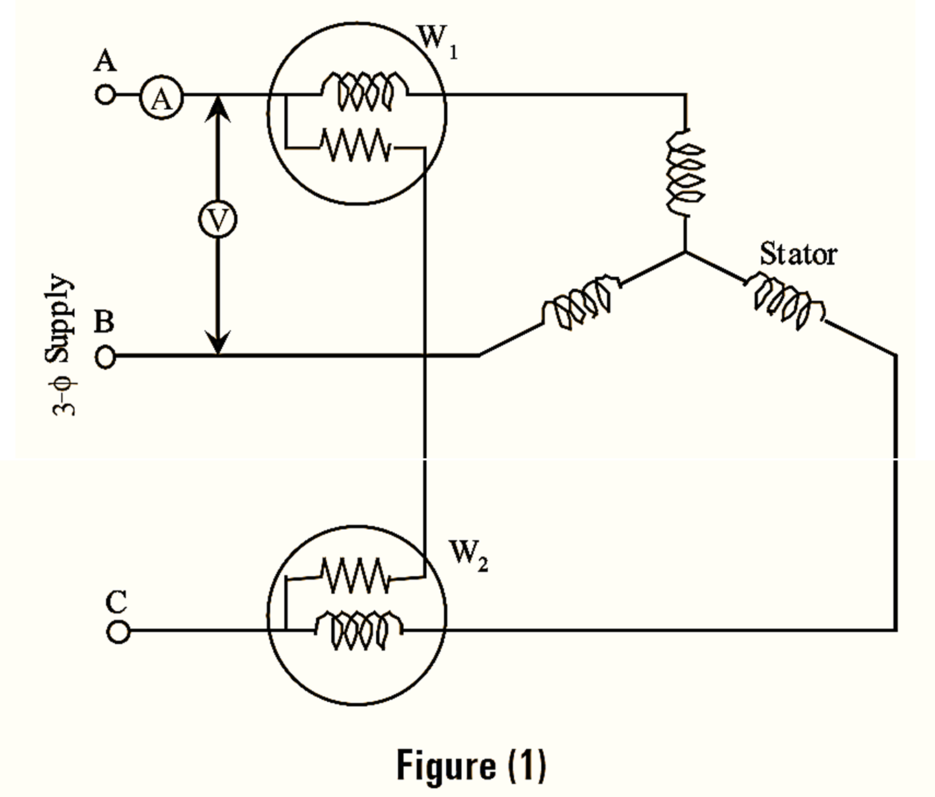
The test is carried out with different values of applied voltage below and above the rated voltage when the motor is running on light load or without load. The input power is measured by two wattmeters, current I0 by an ammeter and voltage V by a voltmeter, which are connected in the circuit as shown in figure (1 As the motor is running on light load the power factor is very low i.e., less than 0.5. Hence, the total power input will be the difference of both the wattmeter readings.
Using,
\[{{W}_{0}}=\sqrt{3}{{V}_{L}}{{I}_{0}}\cos {{\phi }_{0}}\]
\[p.f.=\cos {{\phi }_{0}}\frac{{{W}_{0}}}{\sqrt{3}{{V}_{L}}I}\]
I0 has two components,
\[{{I}_{w}}={{I}_{0}}\cos {{\phi }_{0}}\text{ (Working components)}\]
\[{{I}_{\mu }}={{I}_{0}}\sin {{\phi }_{0}}\text{ (Reactive components)}\]
\[{{R}_{0}}=\frac{{{V}_{L}}/\sqrt{3}}{{{I}_{w}}}\text{ (Iron loss resistance)}\]
\[{{X}_{0}}=\frac{{{V}_{L}}/\sqrt{3}}{{{I}_{\mu }}}\text{ (Magnetizing resistance)}\]
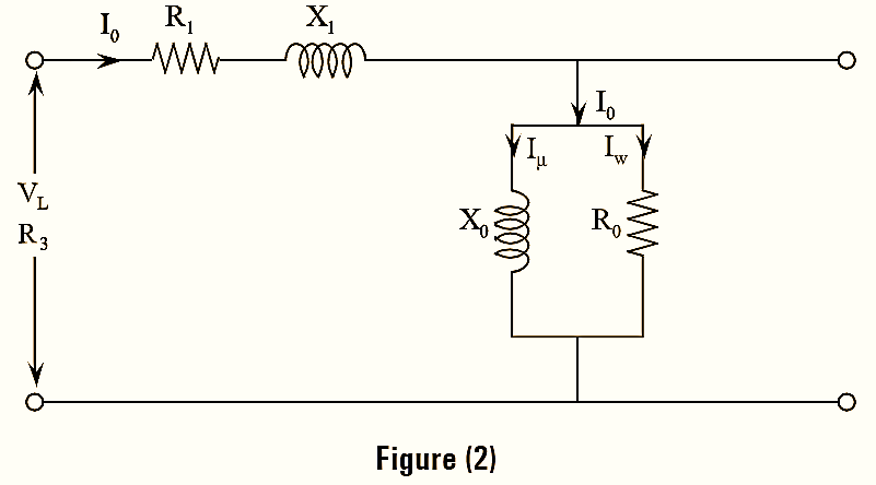
Thus, the equivalent circuit of induction motor on no-load is shown in figure (2).
Blocked Rotor Test
This test is conducted to determine the short circuit current (Isc) with rated current drawn by the stator, power factor on short circuit and equivalent resistance (R01), equivalent reactance (X01) referred to stator side. To obtain rated current reduced voltage is applied to stator. The determined values can be used in the construction of circle diagram of induction motor.
In this test the circuit diagram is same as in no-load test but meters are replaced by higher values. The rotor is held firmly and stator is connected across the variable supply voltage. The readings of voltmeter, wattmeters and ammeter are noted.
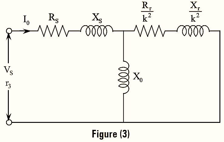
As in this case, power factor is greater than 0.5 both the wattmeter readings are additive for total power. The equivalent circuit diagram under blocked rotor test is shown in figure (3).
Using the relation,
\[{{W}_{sc}}=\sqrt{3}{{V}_{s}}{{I}_{s}}\cos {{\phi }_{sc}}\text{ (Short circuit power)}\]
\[\cos {{\phi }_{sc}}\text{ }=\frac{{{W}_{sc}}}{\sqrt{3}{{V}_{s}}{{I}_{s}}}\text{ (Power factor on short circuit)}\]
\[{{I}_{sN}}={{\left( \frac{V}{{{V}_{s}}} \right)}^{2}}\times {{I}_{s}}\text{ (Current at normal voltage)}\]
\[{{W}_{sN}}=\frac{V}{{{V}_{s}}}\times {{W}_{s}}\text{ (Power at normal voltage)}\]