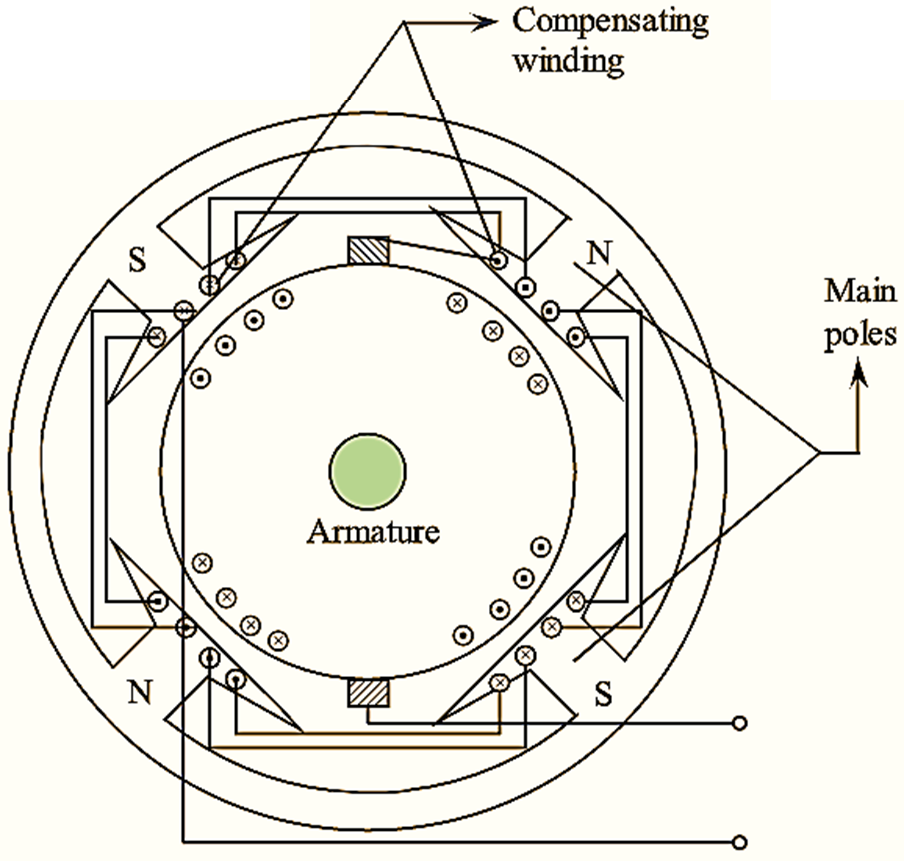
Figure 1: Compensating Winding.
Compensating winding is an extra winding placed in the slots of pole shoes of field winding as shown in figure 1. The armature and compensating winding both are connected in series. In any pole shoe the direction of current in compensating winding is opposite to the direction of current flow through the armature conductors directly below the pole shoe.
A compensating winding is used in order to neutralize the cross-magnetizing effect of armature reaction. The neutralization of cross-magnetizing effect of armature reaction by compensating winding takes place only under the main poles whereas in the interpolar region i.e., the region in between the main poles, there is an incomplete neutralization. But, due to large interpolar gap the effect of armature reaction in interpolar region can be considered as insignificant. Therefore, compensating winding eliminates most of the cross-magnetizing effect of armature reaction.
Armature reaction causes severe distortion in main field flux waveform. The main-field flux waveform becomes non-uniform with peak flux densities at one pole tip of each pole. Whenever any coil passes though the region of peak flux densities a large rotational e.m.f is induced in it. If this rotational e.m.f exceeds the breakdown voltage of commutator segments adjacent to the coil, then an arc is formed. The arc rapidly spreads to nearby commutator segments, this results in flashover of commutator region and complete short circuit of armature. The other factor which may cause flash over and short circuit condition is the variation of armature cross flux (41m) due to sudden fluctuations in load. When any coil comes under the centre of a pole, maximum cross flux links it. The variation of cross flux with sudden change of load can be represented as \(\frac{d{{\phi }_{a}}}{dt}\). According to Faraday’s law, statically induced e.m.f proportional to \(\frac{d{{\phi }_{a}}}{dt}\) is produced in the coil. If this e.m.f exceeds the breakdown voltage of commutator segments adjacent to the coil, then an arc is formed. The arc rapidly spreads to nearby commutator segments, this results in flashover of commutator region and complete short circuit of armature.
The problem of flashover due to distortion of main flux waveform and sudden fluctuations of load can be overcome effectively by neutralization of armature cross flux under the main poles with the help of compensating winding.
Calculation of Compensating Winding Ampere-turns per Pole
The compensating winding neutralizes the armature cross flux only under the main poles. Therefore, the compensating winding ampere turns per pole is given by,
\[\text{A}{{\text{T}}_{\text{CW}}}\text{/ Pole} =\frac{\text{Pole are}}{\text{Pole pitch}}\times \text{ Armature ampere turns per pole}\]
The number of armature conductors per pole = \(\frac{Z}{P}\)
The number of armature turns per pole = \(\frac{Z}{2P}\)
The number of armature ampere turns per pole
\[=\frac{{{I}_{a}}}{A}\times \frac{Z}{2P}\]
\[\text{A}{{\text{T}}_{\text{CW}}}\text{/ Pole}=\frac{\text{Pole are}}{\text{Pole pitch}}\times \frac{{{I}_{a}}}{A}.\frac{Z}{2P}\]