There are many configurations of ac synchronous motors in which semiconductor control is used for controlling the stator currents in such a way that maximum torque is obtained at a given speed. Such configurations can be termed as brushless dc motors (or BLDC motors).

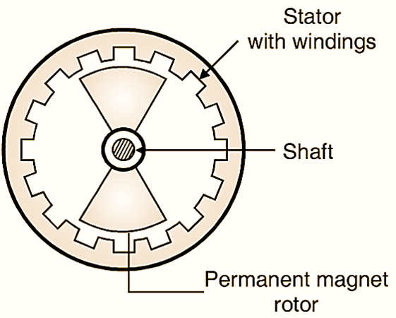
Fig. 1: Construction of BLDC motor.
Construction of BLDC motor
Fig. 1 shows the construction of a BLDC motor, which shows that its construction is similar to that of a permanent magnet synchronous motor. The stator consists of a three phase winding while rotor is in the form of permanent magnets. The BLDC motor also consists of rotor position sensors which produce electrical signals that indicate the existing position of the rotor. The BLDC motor stator winding is driven from an electronic drive which is basically a transistorized three phase inverter. The base driving signals of the transistors connected in the three phase inverter are generated from the rotor position sensors. The speed of the BLDC motor can be controlled by controlling its stator voltage which can be achieved by controlling the dc input voltage of the inverter.
Hall Sensors
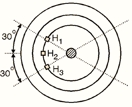
The permanent magnet brushless DC motors use Hall sensors with 60° electrical spacing as shown in Fig. 2. These sensors produce a logic 1 signal when exposed to N pole of the rotor and logic 0 otherwise.

Fig. 2: BLDC Motor Hall Sensors
There are certain similarities between a P.M. synchronous motor and dc motors due to which it is called as a BLDC motor. They are as follows.
- The driver circuit operates on dc supply.
- The fields produced by stator and rotor remain stationary with respect to each other.
- The torque speed characteristics is similar to that of a dc motor.
- This motor does not have brushes (hence the name brushless DC motor).
Types of BLDC motor
The BLDC motor can be of two types:
- Unipolar (half wave) BLDC motor
- Bipolar (full wave) BLDC motor.
Basic Operating Principle of BLDC motor
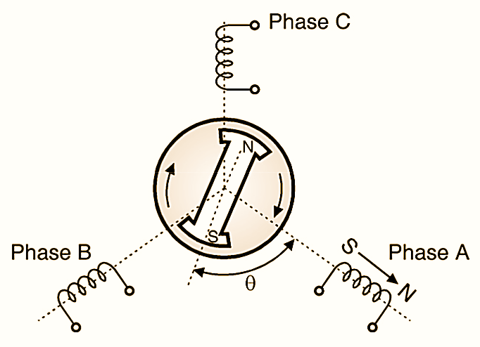
Fig. 3 shows an elementary form of three phase stator winding and a P.M. rotor with two poles. When we energize phase A, the stator poles S and N are created as shown in Fig. 3. Stator S pole repels rotor S pole and attracts rotor N pole. in this way a clockwise torque is produced. The magnitude of this torque is given by,
T = k ΦS ΦR sinθ
Where k = Constant
ΦS = Stator field flux
ΦR = Rotor field flux
θ = Torque angle
This expression shows that the torque is sinusoidally proportional to the torque angle θ. The magnitude of stator filed flux is proportional to stator current I and the rotor field is constant.
T = k1 I1 sinθ
The stator phases are energized in the sequence A, B, C, A so as to have a clockwise rotation of the machine.

Fig. 3: An elementary form of brushless DC motor
Advantages of BLDC Motor
- Electronic control of speed and torque is possible.
- Reduced problems related to the electromagnetic interference
- Efficiency is generally Higher .
- Mechanical commutator and brushes are not present. Hence low maintenance and long life.
- It is possible to vary the speed in a stepless smooth manner.
- BLDC motors run at much higher speeds.
- It is possible to vary the (torque by adjusting the stator currents.
Applications of BLDC Motor
- These motors are used for turn (able drives for record players, hard disc drives etc.
- They are also used in aircraft and satellite systems.