The armature windings are the conductor coils placed in the slots of armature core mounted on the shaft of the rotor of a D.C machine. As the e.m.f induced for one turn is very small, each coil of the winding consists of many turns to get the required e.m.f.
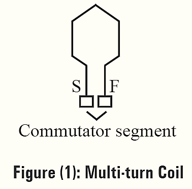
The coils with many turns are known as multi-turn coils as shown in figure (1). These coils are diamond shaped with start (S) and finish (F) ends. These ends are terminated on commutator segments. The positions of coil sides are, one side of a coil is placed in the upper half of a slot and the other side of a coil in the lower half of another slot. Similarly, it is vice versa for another coil in the same slots. This is a double layered winding arrangement generally used on any D.C machine. A coil rotated in a magnetic field induces current. The current is in same direction in both the sides of the coil. Hence, during rotation when one side of the coil comes under north pole, the other side of the coil comes under south pole. The displacement between the sides of the coil is called the coil span. It is one pole pitch.
\[\text{Coil span = }\frac{\text{Number of slots}}{\text{Number of poles}}\]
Also,
Number of commutator segments = Number of armature coils.
Types of Armature Winding
There are two types of armature windings. They are,
- Lap winding
- Wave winding.
Lap Winding
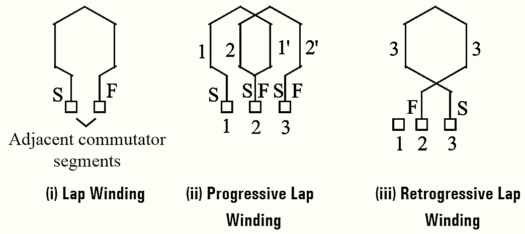
Figure 2: Lap Winding.
In lap winding, the start and finish ends of the coil of an armature winding terminate on two adjacent commutator segments.
When the start end terminates on a commutator segment and the finish end terminates on the next forward segment, it is called a progressive lap winding. If the finish end terminates on a segment before the start end segment, it is called a retrogressive lap winding as shown in figure (2).
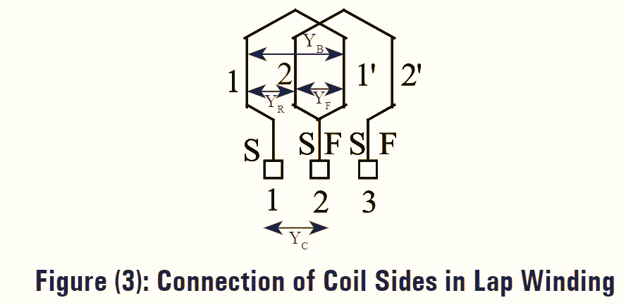
In lap winding, the number of parallel paths A is equal to the number of field poles P i.e., A = P. In lap winding, connections of coil sides are as shown in figure (3).
At the back end of armature, the back pitch (YB) is added to the coil side that is to be connected. For example, the coil side 1 is to be connected to coil side 1 + YB i.e., 1’ Whereas, at the front end of armature i.e., at the commutator side, the front pitch (YF) is subtracted from the coil side that is to be connected. For example, the coil side 1′ is connected to coil side 1′ — YF i.e., 2. Similarly, the remaining coils are connected continuously. As the two sides of a coil are connected to neighboring commutator segments, the commutator pitch (YC) is equal to 1 for lap winding. The resultant pitch (YR) which is the distance between the beginning of one coil and the beginning of next coil is given by YR = YB — YF.
Wave Winding
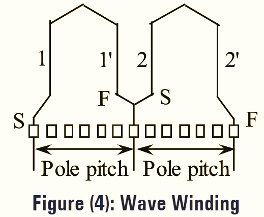
In wave winding, coils are connected in series. The finish of first coil is connected to the start of the second coil placed under adjacent pole. The winding progresses in the same way for the next coils till it comes back to the stalling slot. Therefore, irrespective of the number of poles there are two parallel paths between the negative and the positive terminals of the armature.
Hence, in wave winding, the number of parallel paths A is always 2 irrespective of the number of field poles i.e., A = 2. In wave winding, connections of coil sides are as shown in figure (4). At the back end of armature, the back pitch (YB) is added to the coil side that is to be connected. For example, the coil side 1 is to be connected to coil side 1 + YB i.e., 1′. Whereas, at the front end of armature i.e., at the commutator side, the front pitch (YF) is added to the coil side that is to be connected. For example, coil side l’ is connected to coil side 1′ + YF i.e, 2. Similarly, the remaining coils are connected continuously. The commutator pitch (YC) in wave winding is the average of back pitch and front pitch. The resultant pitch (YR) which is the distance between beginning of one coil and the beginning of next coil is given by YR = YB + YF.
Difference between Lap Winding and Wave Winding
|
Lap Winding |
Wave Winding |
| The winding in which the end of one coil is connected by means of commutator segment to the beginning of adjoining coil placed under the same pole is known as lap winding. | The winding in which the end of one coil is connected by means of commutator segment to the beginning of other coil placed under the adjacent pole is known as wave winding. |
| In this winding the coil sides of neighboring coils over- lap and hence the name lap winding. | In this winding the appearance of connections of coils is like a wave and hence the name wave winding. |
| The resultant pitch (YR) is equal to difference of back pitch (YB) and front pitch (YF). | The resultant pitch (YR) is equal to sum of back pitch (YB) and front pitch (YF). |
| The number of parallel paths is same as the number of poles i.e., A = P. | It always has two parallel paths and is independent of the number of poles i.e., A = Z. |
Back Pitch
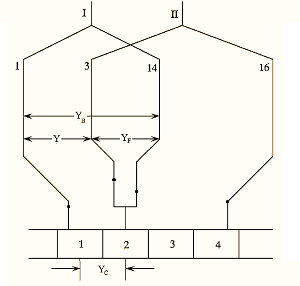
Figure 5.
It is defined as the distance which is measured in the form of armature conductors when a coil advances on the back of the armature. It is denoted by “YB“. The size of the coil is decided by the back pitch. For a lap winding shown in figure (5). The coil I has coil sides as 1 and 14.
Back pitch, YB = 14 – 1 = 13
Front Pitch
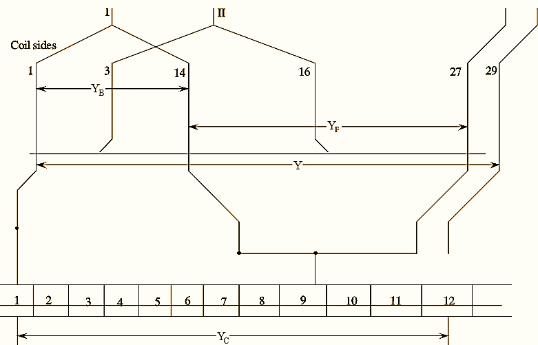
Figure 6.
It is defined as the distance measured between the second conductor of one coil and the first conductor of the adjacent coil which are coupled together to the same commutator segment of the armature. It is denoted by “YF”
The front pitch for the lap winding and wave winding is shown in figure (5) and figure (6) respectively. From figure (5), the front pitch, YF = 14 – 3 = 11 and from the figure (6), the front pitch is 27 – 14 = 13. Thus, the front pitch (YF) for both lap and wave winding is an odd number.