A PN junction diode that acts as a voltage variable capacitor under reverse bias condition is known as varactor diode. The symbol and its equivalent circuit of varactor diode are as shown in figure (1).

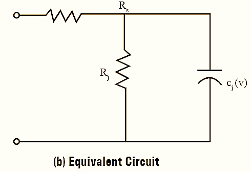
Figure 1: Varactor Diode.
Working Principle of Varactor Diode
Junction capacitance present in all reverse biased diodes because of depletion region is optimized in a varactor diode and used in high frequencies and switching applications. In other words, the dependence of junction capacitance, Cj on the reverse bias voltage, V is made useful in a number of applications like in radio receiver for frequency tuning of oscillators, telephones, TV receivers, wireless LAN radios.
The depletion layer created in the PN junction acts as an insulator and the P-region and N-region act as plates of the capacitor. When the reverse voltage increases. the width of depletion layer increases and capacitance becomes smaller. The capacitance CT of a varactor diode is determined using the equation.
The variations in the capacitance Cj with respect to the bias voltage V are computed using the formula,
\[{{C}_{j}}(V)=\frac{{{C}_{0}}}{{{(1-V/{{V}_{0}})}^{\gamma }}}\]
Where,
C0 and V0 are constants.
γ — Exponent ranges from 1/3 to 5.
The value of γ depends on the doping level of the semiconductor and it is 0.5 for constant doping. From figure (1), Rj is the junction resistance which is about 1 MΩ in reverse bias condition. Usually, the series junction or contact resistance Rs, is very much less than Rj.
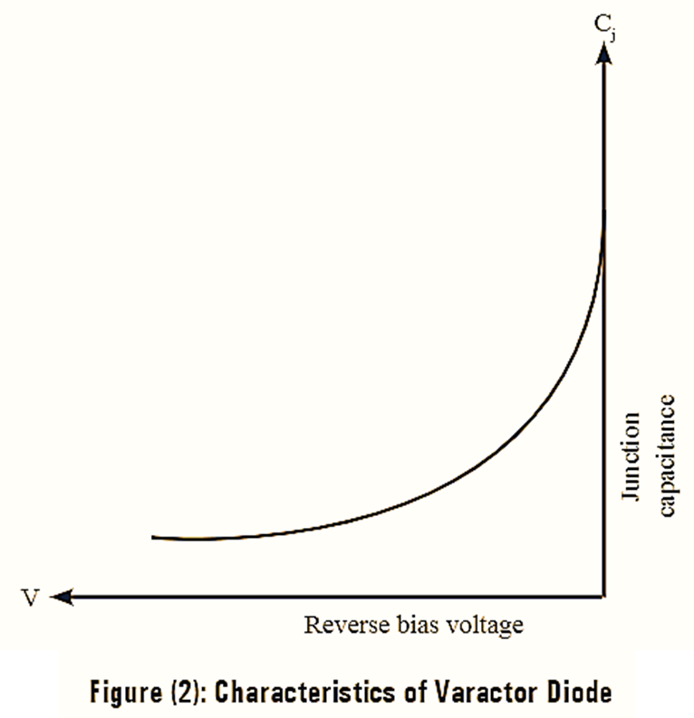
The characteristics of varactor diode are as shown in figure (2).
Applications of Varactor Diode
- It is used in parametric amplifiers to amplify the signal.
- Varactor diode up converts the microwave frequencies.
- It is used to generate the pulse and in pulse shaping techniques.
- In radio receivers, instead of using a variable capacitor in tuners varactor diode is used.
- For generating harmonic waves.
- Instead of reactive elements, varactor diodes are used in active filters.
- Variable reactor in microwave circuits.
- Varactor is used as frequency modulator in radios and television sets.