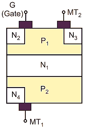
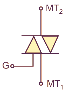
TRIAC is a bilateral power device which operates in both the forward and reverse mode. Its operation is similar to two parallel SCRs connected in opposite direction with a common gate terminal as shown below. The construction shown in Fig. 1 (a) and symbol as shown in 1 (b).
(a)
(b)
Fig. 1: Construction and Symbol of TRIAC.
Operation of TRIAC
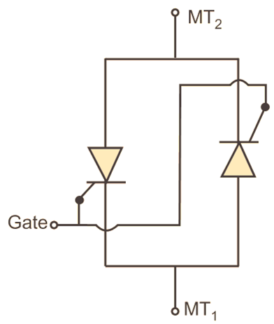
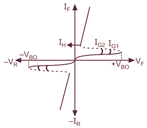
As the TRIAC is equivalent to two SCRs connected in parallel its characteristic is similar to that of an SCR (Fig 2(a). If the gate is open and MT2 is made positive with respect to MT1, the device remains OFF until the forward breakover voltage (VBO) is reached (Fig 2(b). This is the forward blocking region of the TRIAC. Beyond VBO the TRIAC conducts heavily. Now, if the gate is open and MT1 is made positive with respect to MT2, the device remains off until the reverse breakover voltage (VBR) is reached. This is the reverse blocking region of the TRIAC. Beyond VBR the TRIAC conducts heavily in opposite direction. The Gate terminal can be supplied with voltage of appropriate magnitude and polarity to trigger the TRIAC at lower magnitude of forward or reverse voltages between MT1 and MT2. Thus a TRIAC can be used as a switch and phase control device.
(a)
(b)
Fig. 2: Equivalent Circuit and V-I Characteristics of TRIAC
The main difference between TRIAC and SCR is that a TRIAC is a bidirectional device whereas SCR is Unidirectional. Also a TRIAC can be triggered into conduction by applying either a positive or negative voltage to the gate with respect to MT1 whereas the SCR can be triggered by applying positive gate trigger only.
Triggering Modes of TRIAC
- Terminal MT2 is made positive with respect to MT1, with a positive voltage between gate and MT1: In this mode the TRIAC behaves as conventional SCR.
- Terminal MT2 is made positive with respect to MT1, with a negative voltage between gate and MT1: In this mode the TRIAC switches ON by an operation called junction gate operation. Even if the gate current is negative, the TRIAC operates in first quadrant. This form of gate drive is not normally used because it involves high switching therefore.
- Terminal MT2 is made negative with respect to MT1. with a positive voltage between gate and MT1: In this mode, the TRIAC operates in the third quadrant. And the characteristic is exact replica of that of the conventional SCR in third quadrant.
- Terminal MT2 is made negative with respect to MT1, with a negative voltage between gate and MT1: In this mode, the TRIAC operates in the third quadrant. The gate current is negative. This mode is recommended for application of a negative gate pulse.
Advantages of TRIAC
- Gives power control in both directions due to the ability to conduct in both directions.
- Can withstand high voltage and currents.
- No external commutation circuitry is required.
- Less expensive.
Disadvantages of TRIAC
- Not suitable for D.C. power control.
- Similar to SCRs, in TRIACs also, the gate loses its control once the device is ON.
- Very small switching frequencies.
Applications of TRIAC
- Light dimmers.
- Static switches.
- Temperature controllers.
- Heat controllers.
- A.C. Power flashers.
- Power controllers for loads.
- Proximity detector circuits.