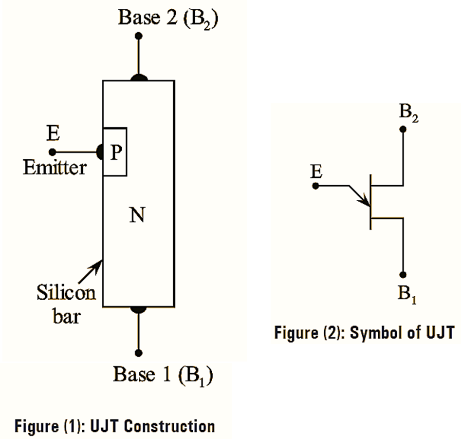
UJT is an acronym for Unijunction Transistor. The basic structure of a unijunction transistor is as shown in figure (1). It contains a lightly doped N-type silicon bar on which a small portion of heavily doped P-type material is alloyed. The P-type material doped into the N-type bar forms a single P-N junction. Because of this, it is known as unijunction. The N-type bar has two ohmic contacts at its ends named as base-1(B1) and base-2(B2) and the ohmic contact coming out of P-region is named as emitter (E). The emitter junction is created (or produced) closer to base-2 (B2) than base-1(B1), so the device is not symmetrical. The symbol for the transistor is shown in figure (2). The emitter leg is drawn at an angle to the vertical line representing the N-type material slab and the arrowhead indicates the direction of conventional current flow when the transistor is operating in the active region.
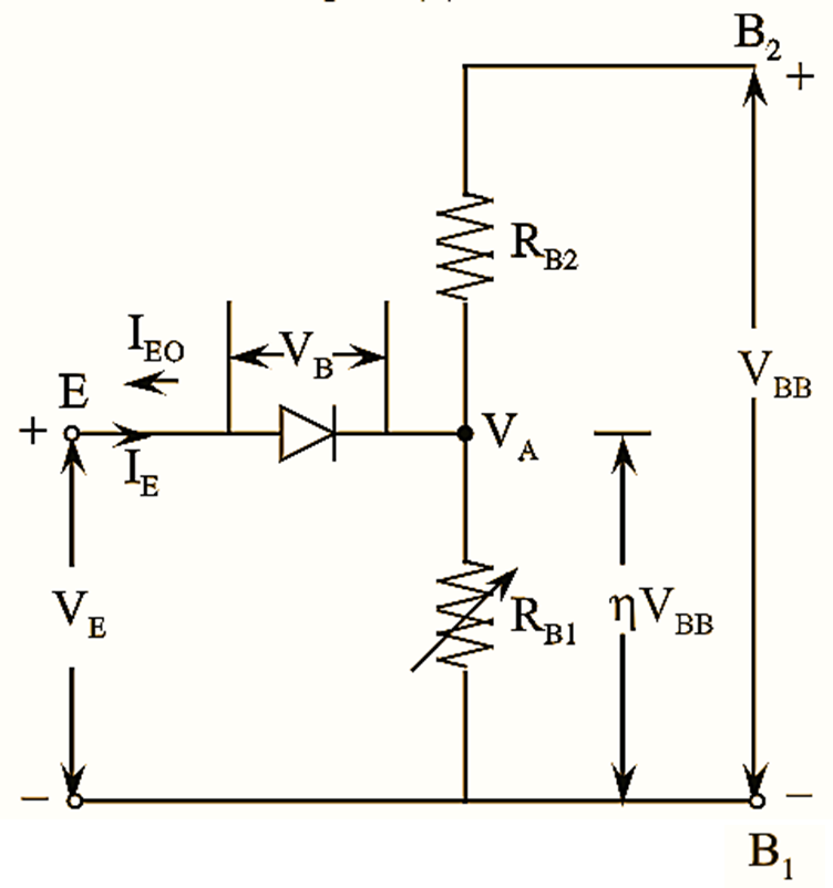
The basic UJT circuit includes a diode and two base resistances RB1 and RB2, in which RB1 is a variable resistor. The value of RB1 varies between 5 kΩ and 50 Ω with the change in emitter current from 0 µA to 50 µA.
VI Characteristics of Unijunction Transistor (UJT)
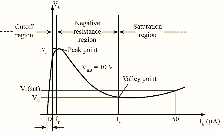
Figure 3: VI Characteristics of Unijunction Transistor (UJT).
The forward and reverse operating conditions or ON and OFF states of UJT depends on the emitter voltage VE,
(i) If the voltage at emitter terminal VE is not sufficient to turn ON the diode, it acts as an open switch and small leakage current IE0 flows through the circuit. In this case, the transistor operates is in cut-off region and emitter current IE = 0.
The resistance between the terminals B1 and B2 for IE = 0 is given by,
\[{{R}_{BB}}={{R}_{B1}}+{{R}_{B2}},{{I}_{E}}=0\]
Here,
RBB — Interbase resistance
Using voltage-divider rule, the potential drop across RB1 is determined as,
\[{{V}_{{{R}_{B1}}}}=\frac{{{R}_{B1}}}{{{R}_{B1}}+{{R}_{B2}}}{{V}_{BB}}\]
\[=\frac{{{R}_{B1}}}{{{R}_{BB}}}{{V}_{BB}}\]
\[=\eta {{V}_{BB}}\]
Where,
η — Intrinsic stand-off ratio
\[\eta =\frac{{{R}_{B1}}}{{{R}_{B1}}+{{R}_{B2}}}=\frac{{{R}_{B1}}}{{{R}_{BB}}}\]
(ii) The emitter voltage, VE reaches to peak point, when the voltage applied is greater than ηVBB + VB (VB is the diode cut-in voltage). At this point, the UJT tum ON i.e., conducts and IE increases. But, the voltage VE reduces due to negative resistance characteristics.
(iii) When emitter voltage, VE from peak point reaches valley point, VV the transistor enters into saturation region.
The characteristics of UJT are plotted as shown in figure (3). From figure (3), it can be observed that, in negative resistance region or active region the voltage VE reduces with increase in current IE. In this region, when UJT starts conducting, the holes from P-type material are injected into N-type silicon bar. During this, the number of free electrons increases in N-type slab due to increased hole concentration, high conductivity takes place in transistor. Thus, the UJT exhibits negative resistance characteristics i.e., resistance decreases with increase in conductivity.
Applications of Unijunction Transistor (UJT)
- UJT is used as a relaxation oscillator to generate sinusoidal waveforms.
- It is widely used as sawtooth generator, sweep oscillator, and voltage detector.
- Magnetic flux can be measured using UJT.
- It is used in phase controllers and timing circuits.
- In SCRs and Triac, UJT is used as a triggering circuit.