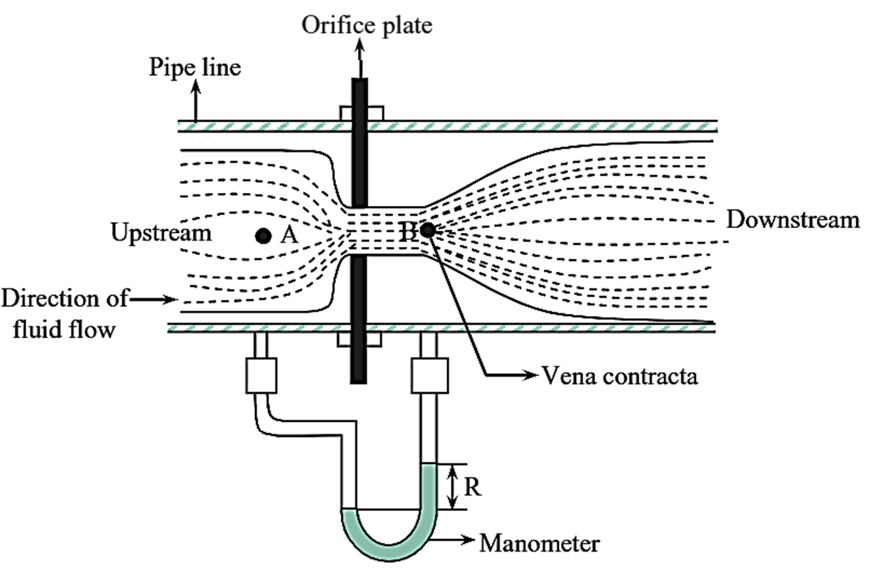
Figure 1: Orifice Meter.
An orifice meter is a device used to measure the flow rate of a fluid (liquid or gas) through a pipeline. Orifice meter is a thin plate with a central narrow aperture which is introduced in a pipeline. Thus, when a fluid stream passes through the narrow constriction of the orifice, the velocity (i.e., kinetic energy) of the fluid at the orifice plate increases in comparison with its velocity at the entry of the pipe. Thus, the corresponding pressure energy decreases. The reduction in pressure can be measured by the manometer.
Working Principle of Orifice Meter
According to the Bernoulli’s theorem, the increase in the velocity head with the decrease in pressure head can be correlated between the two points i.e., where the manometer is arranged in a pipeline. The velocity of the fluid at the point (before entering the orifice) can be neglected due to the smaller diameter of the orifice than pipe diameter. In such a case, the velocity of the fluid is directly read from the manometer. The velocity of the fluid at the orifice can be calculated from the following formula.
\[{{u}_{0}}=\sqrt{2{{g}_{c}}\Delta H}……(1)\]
Where,
u0 = Fluid velocity at the point of orifice
C0 = Constant of orifice meter
ΔH = Difference in pressure head, m.
This is the simplest and widely used pressure differential flow meter. It consists of a thin plate with a central narrow aperture, which is smaller in diameter than the pipeline in which it is introduced. To measure the pressure difference, the manometer is connected to the pipe. The orifice meter can be placed in the side or bottom of the pipeline.
Working of Orifice Meter
When the fluid is introduced in the pipe, it passes through the narrow constriction of the orifice meter. Two points A and B are chosen in the orifice meter to demonstrate the velocity of the fluid flowing through the orifice. The fluid leaves the constriction of the orifice meter at point B with a velocity higher than the velocity at point A. Thus, the corresponding pressure head at point B is less than the pressure head at point A. The pressure difference (ΔH) is read from the manometer which is arranged at the points A and B.
The Bernoulli’s equation is applied for the two points A and B in the orifice meter as follows,
\[\sqrt{u_{0}^{2}-u_{A}^{2}}={{C}_{0}}\sqrt{2{{g}_{c}}.\Delta H}\]
Where,
u0 = Fluid velocity at the point of orifice meter, m/s
uA = Fluid velocity at the point A, m/s
C0 = Constant
ΔH = Pressure difference, m.
When the diameter of the orifice is very less compared to the diameter of the pipe, then velocity of the fluid at point A (uA) is less compared to the velocity of the fluid at the constriction (u0). Hence, uA is ignored.
Thus, equation (1) becomes
\[\sqrt{u_{0}^{2}}={{C}_{0}}\sqrt{2{{g}_{c}}.\Delta H}\]
\[{{u}_{0}}={{C}_{0}}\sqrt{2{{g}_{c}}.\Delta H}……(2)\]
The value of ‘ΔH’ is read from the manometer and substituted in equation (2) to calculate the velocity of the fluid flowing through the orifice meter, provided that the cross section of the pipe is known. The volume of the fluid flowing per hour is calculated.
In the above stated experimental conditions, the Bernoulli’s theorem is applied as follows.
\[{{X}_{A}}+\frac{u_{A}^{2}}{2{{g}_{c}}}+\frac{{{P}_{A}}}{g{{\rho }_{A}}}-F+W={{X}_{B}}+\frac{u_{B}^{2}}{2{{g}_{c}}}+\frac{{{P}_{B}}}{g{{\rho }_{B}}}……(3)\]
In the above equation, the following assumptions can be made to the orifice meter.
- XA = XB because the heights of the points A and B are same and hence the terms get cancelled.
- F = 0, friction losses are not appreciable and considered negligible.
- ρA = ρB = ρ, because the fluid flowing through the orifice is the same.
- W = 0, no work is done by the liquid.
The equation (3) is reduced to,
\[\frac{u_{A}^{2}}{2{{g}_{c}}}+\frac{{{P}_{A}}}{g\rho }=\frac{u_{B}^{2}}{2{{g}_{c}}}+\frac{{{P}_{B}}}{g\rho }\]
\[\frac{u_{B}^{2}}{2{{g}_{c}}}-\frac{u_{A}^{2}}{2{{g}_{c}}}=\frac{{{P}_{A}}}{g\rho }-\frac{{{P}_{B}}}{g\rho }\]
\[\frac{1}{2{{g}_{c}}}(u_{B}^{2}-u_{A}^{2})=\frac{1}{u_{B}^{2}}({{P}_{A}}-{{P}_{B}})\]
\[u_{B}^{2}-u_{A}^{2}=\frac{2{{g}_{c}}}{g\rho }({{P}_{A}}-{{P}_{B}})\]
\[u_{B}^{2}-u_{A}^{2}=\frac{2{{g}_{c}}}{g\rho }.\Delta P\text{ }\left[ {{P}_{A}}-{{P}_{B}}=\Delta P\text{ } \right]\]
\[u_{B}^{2}-u_{A}^{2}=2{{g}_{c}}.\Delta H\text{ }\left[ \frac{\Delta P}{g\rho }=\Delta H\text{ } \right]\]
To nullify the differences between the velocities at orifice and at vena contracta (point B) a constant, C0 is included.
\[\sqrt{u_{B}^{2}-u_{A}^{2}}={{C}_{0}}\sqrt{2{{g}_{c}}.\Delta H\text{ }}\]
The velocity through the orifice is u0.
\[\sqrt{u_{0}^{2}-u_{A}^{2}}={{C}_{0}}\sqrt{2{{g}_{c}}.\Delta H\text{ }}\]
uA, is negligible as the orifice diameter is 1/5 th of the pipe diameter or less.
\[{{u}_{0}}={{C}_{0}}\sqrt{2{{g}_{c}}.\Delta H\text{ }}\]
Advantages of Orifice Meter
- It is a simple machine having low cost.
- It requires less space.
- Easy to install and interchange.
- Adjustable orifices are available.
Disadvantages of Orifice Meter
- Permanent loss of pressure.
- When the ratio of orifice to pipe diameter is above 0.75, the results are not accurate.
- If the fluid contains solid particles, it may obstruct the orifice.
- The orifice meter is not recommended above 1000 psi at 800ºF.
Applications of Orifice Meter
The velocity of the fluid at the two points (A and B) can be calculated. The volume of the fluid flowing per hour can be determined provided that the velocity of the fluid at point A (uA) and cross-section of the pipe are known. Orifice meters are used in industries like oil and gas, water treatment, power, and HVAC for measuring fluid and gas flow. Applications include natural gas pipelines, boiler feed water, steam, chemical processing, slurry flow, and air systems. They’re cost-effective, reliable, and versatile for diverse industrial and commercial flow measurement needs.