Megger is a portable instrument for measuring high resistances in which the voltage range can be controlled by using a voltage selector switch. It is not only used for measurement of high resistances (insulation resistance), but also can be used for testing of insulation resistance. One more advantage is that deflection of the instrument is independent of magnetic field strength. It is calibrated directly in mega ohms and also it is known as mega ohmmeter.
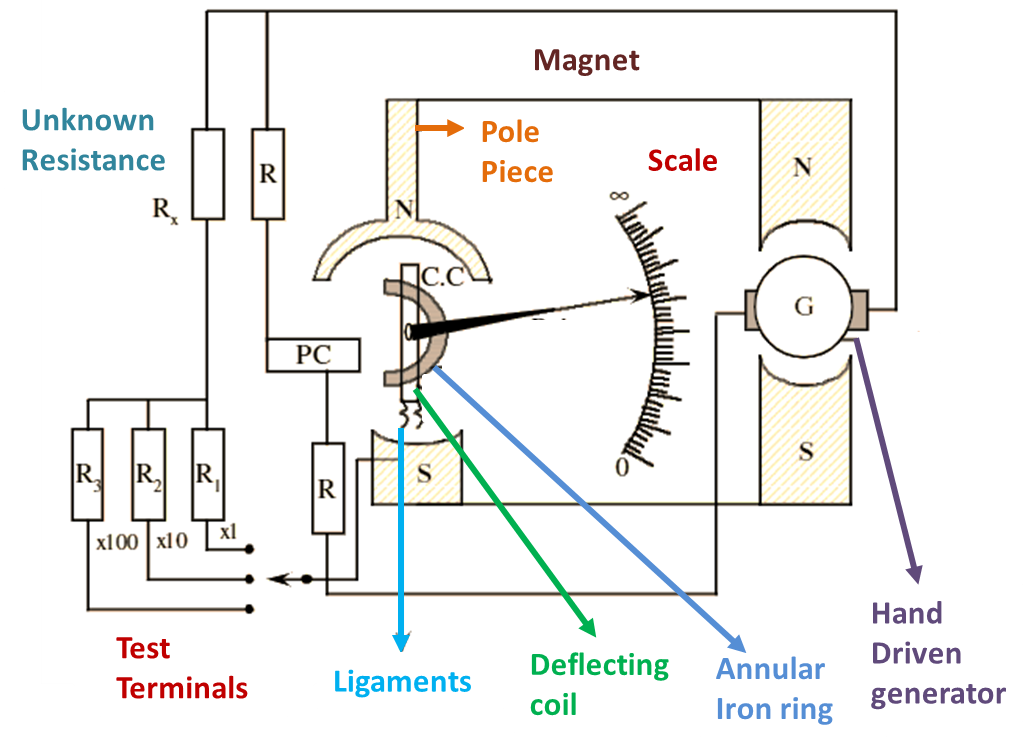
Fig, 1: Internal Diagram of Megger.
Working Principle of Megger
The principle of working of megger is based on electromagnetic induction. When a conductor carrying current is kept in a magnetic field. then the conductor exerts a force which is proportional to the strength and capacity of the current and magnetic field. The direction of the force is along the direction of current and magnetic field.
Construction of Megger
Megger consists of current coil or PMMC instrument and pressure coils (see Fig. 1). There are two pressure or voltage coils. All these coils are placed around an annular iron ring on a common shaft which rotates freely. Ligaments are the flexible leads which connect the coils. The C-shaped iron core has a deflecting coil on to which pointer is attached. The pointer indicates the deflection over the graduated scale. A hand driven generator is provided in instrument in order to generate the operation of megger. If the scale is calibrated in reverse, the pointer indicates ‘∞’ and if the scale is fully deflected, then the pointer indicates ‘0’ resistance.
Working of Megger
Current is passed to the coils from the hand driven generator. The pressure coils are set in such a way that it stands perpendicular to the magnetic field. If the test terminals are kept open corresponding to ‘∞’ Ω then the current does not flow through the coil (deflection). The pressure coil controls the movement of deflecting coil and makes it to come in opposite direction, when the pointer is at ‘∞’ position, small torque is exerted by the coil. If the test terminals are kept shorted corresponding to ‘0’ Ω, then the large current flows through the deflecting coil. The torque exerted by the coil is increased by making it to move in strong magnetic field. When the pointer is at ‘0’ position, maximum torque is exerted under the pole piece.
The effect of this instrument decreases the “low resistance” and sets up ‘high resistance” portion of the scale. This effect is beneficial to use as insulation test because the insulation resistances are large.
Applications of Megger
- Megger checks the continuity between any two points in a circuit.
- It determines the resistance between the equipment and the earth.
- It performs the various tests in industries such as.
(i) Open circuit (O.C.) tests
(ii) Short – circuit (S.C.) tests
(iii) Ground tests.