A double cage rotor induction motor gives excellent starting and running characteristics than a deep-bar cage rotor induction motor. It also provides a high starting torque with a low starting current. Therefore it is also known as low-starting current, high starting torque, low slip-motor. The rotor is well designed in order to have high resistance rotor circuit during starting and low resistance rotor circuit when operating at running conditions.
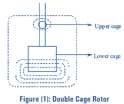
Construction of Double Cage Induction Motor
In double cage rotor induction motor, the stator is similar to that of ordinary induction motor. The only difference is in the rotor construction. The rotor of double cage induction motor is constructed by using two sets of squirrel cage windings which are provided on the rotor separated by narrow slit or construction. The upper cage or the starting cage which is very close to the air gap is made of high resistivity material such as aluminium, bronze etc., and the lower cage is made up of copper. The cross- section of upper cage is smaller than the lower cage and hence the resistance of upper cage is higher than that of lower cage. Common short circuiting end lings can be provided for both the cages or separate short circuit end ring can be provided for each of the cage. The schematic of a double cage rotor is shown in figure (1). Double cage induction motor has two cages on the same rotor i.e., a high resistance and low reactance bars on outer cage and low resistance and high reactance bars on inner cage respectively.
Working of Double Cage Induction Motor
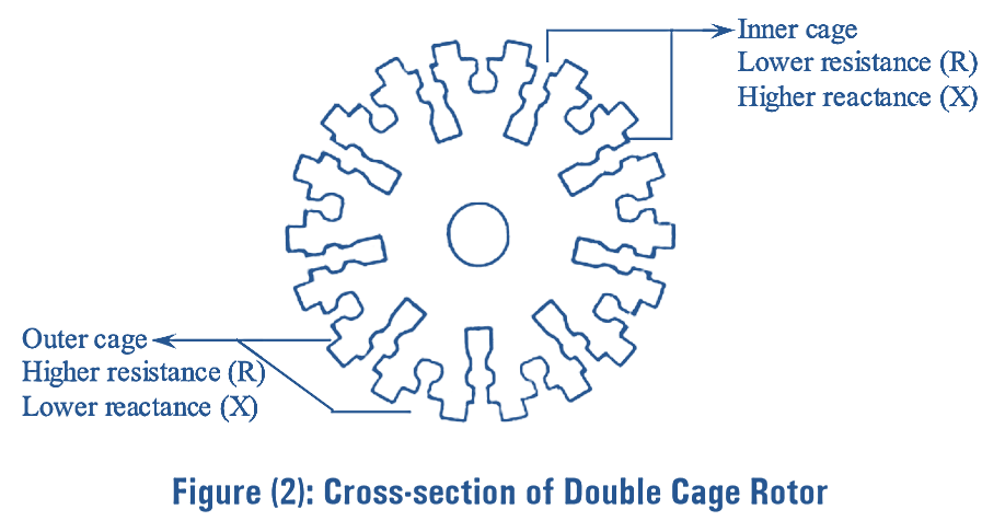
The cross-sectional view of double cage induction rotor is shown in figure (2). Initially, the rotor current frequency is high due to large slip, which is nearly equal to supply frequency. The current supplied to inner and outer cages of rotor will be inversely proportional to their impedance. However, the inner cage have a high impedance compared to outer cage due to its high leakage reactance. Thus, the current in inner cage is small but the outer cage current is enclosed which has a high resistance. This gives a very good starting torque.
When the speed of the motor is increased, the frequency of the rotor current gets decreased. Thus, the leakage reactance of inner cage is reduced when the motor is running at full speed. Therefore, the reactances of both the cages become too small and the current is divided in the ratio of resistances (i.e., the resistance of outer cage is 5 to 6 times of inner cage). Further, maximum current flows in inner cage and the motor runs at low slip.
Torque-speed Characteristics of Double Cage Induction Motor
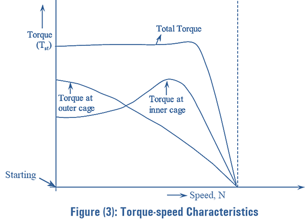
Figure (3) shows the torque-speed characteristics of double cage induction motor. From figure (3), it can be seen that, the outer cage provides a high starting torque whereas the inner cage helps in obtaining the sufficient speed at the normal running condition. Hence, both characteristics combined provide an excellent torque-speed characteristic curve. Due to these characteristics, double cage induction motor is also known as low starting current, high starting torque, low slip motor.
Equivalent Circuit of Double Cage Induction Motor
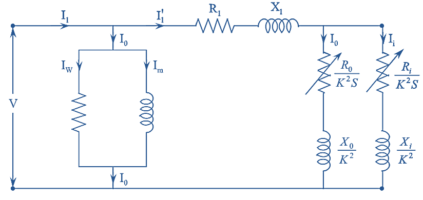
Figure 4.
The equivalent circuit diagram referred to stator of a double cage induction motor is shown in figure (4).
Where,
R1 – the per phase stator resistance
X1 — the per phase stator reactance
Ri — the inner cage resistance/phase referred to stator
Xi — the inner cage reactance/phase referred to stator
R0 — Outer cage resistance/phase
X0 — Outer cage reactance/phase
Iw — Working component of current
Im – Magnetizing component of current
K — Transformation ratio and
s — The considered slip.
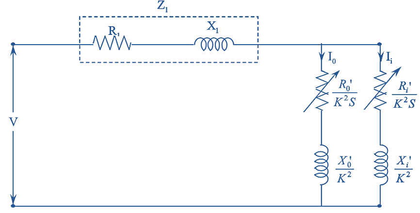
Figure 5.
In figure (5), if the magnetizing current is not considered and neglected, then the equivalent circuit of double cage induction motor changes to as shown in figure (5).
Where,
\({{{{R}’}}_{0}}\) is the outer cage resistance/ph referred to stator
\({{{{X}’}}_{0}}\) is the outer cage reactance/ph referred to stator.
The total impedance referred to stator is given by,
\[{{Z}_{01}}=({{R}_{1}}+j{{X}_{1}})+\frac{1}{\frac{1}{{{{{Z}’}}_{i}}}+\frac{1}{{{{{Z}’}}_{0}}}}\]
\[={{R}_{1}}+j{{X}_{1}}+\frac{1}{\frac{{{{{Z}’}}_{0}}+{{{{Z}’}}_{i}}}{{{{{Z}’}}_{i}}.{{{{Z}’}}_{0}}}}\]
\[{{Z}_{01}}={{R}_{1}}+j{{X}_{1}}+\frac{{{{{Z}’}}_{0}}.{{{{Z}’}}_{i}}}{{{{{Z}’}}_{0}}+{{{{Z}’}}_{i}}}\]
Advantages of Double Cage Induction Motor
- It reduces the starting current.
- It increases the starting torque.
Disadvantages of Double Cage Induction Motor
- Maximum torque is less.
- Power factor is low.
- Efficiency is less.
- Rotor copper losses are high.
- Cost is high.