A DC Machine is an electromechanical device that enables the conversion of energy between mechanical and electrical forms. When it operates as a generator, it transforms mechanical input power into electrical output power. When functioning as a motor, it performs the opposite conversion – turning electrical energy supplied to it into mechanical motion.
DC machines have been used for decades in industrial drives, traction systems, instrumentation, control systems and energy conversion applications due to their simple construction and ease of control. Although modern AC drives are popular today, DC machines still play an essential role in many engineering and academic fields.
Definition of a DC Machine
A DC machine is a device that either converts mechanical energy to electrical energy or electrical energy to mechanical energy when supplied with direct current. Based on its mode of operation, it is classified into:
- DC Generator – Converts mechanical power into DC electrical power.
- DC Motor – Converts DC electrical power into mechanical rotational motion.
Structurally, there is no fundamental difference between a DC generator and a DC motor. The same machine can operate as either depending on how it is connected to the external system.
DC Machine Working Principle
Working Principle of a DC Generator
When the armature conductors of the machine rotate inside the magnetic field created by the field windings, they cut magnetic flux. According to Faraday’s Law of Electromagnetic Induction, an induced emf develops in these conductors. The magnitude of this emf depends on the rate of flux cutting and the number of turns.
The emf generated inside the armature is alternating in nature, but the presence of the commutator converts it into a unidirectional (DC) voltage at the terminals of the generator.
Working Principle of a DC Motor
When a DC supply is applied to the armature conductors placed in a magnetic field, electric current flows through them. As per Fleming’s Left-Hand Rule, a mechanical force acts on every current-carrying conductor inside the magnetic field. The combined force produces rotational motion of the armature.
As the armature rotates, an induced emf is also produced in the winding which opposes the supply voltage. This is known as Back EMF (Eb), and it plays an important role in regulating armature current and motor speed.
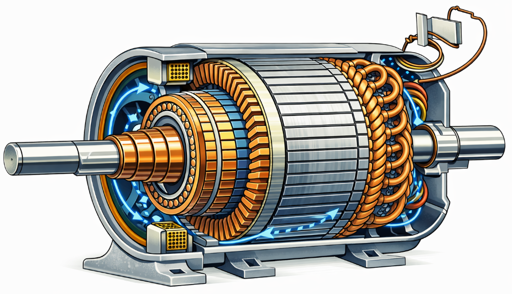
Construction of a DC Machine
A DC machine — whether operating as a motor or generator — consists of several essential components designed to create and utilize magnetic and electrical interactions. The main parts include:
- Field Windings
- Yoke and Poles
- Armature Core and Armature Windings
- Commutator
- Brushes
- Rotor Shaft
1. Field Windings
The field windings are mounted on the pole cores and produce alternating north and south poles when current flows through them. They act as electromagnets and generate the primary magnetic field required for machine operation. The windings are generally made of high-conductivity copper wire.
2. Armature Core and Armature Windings
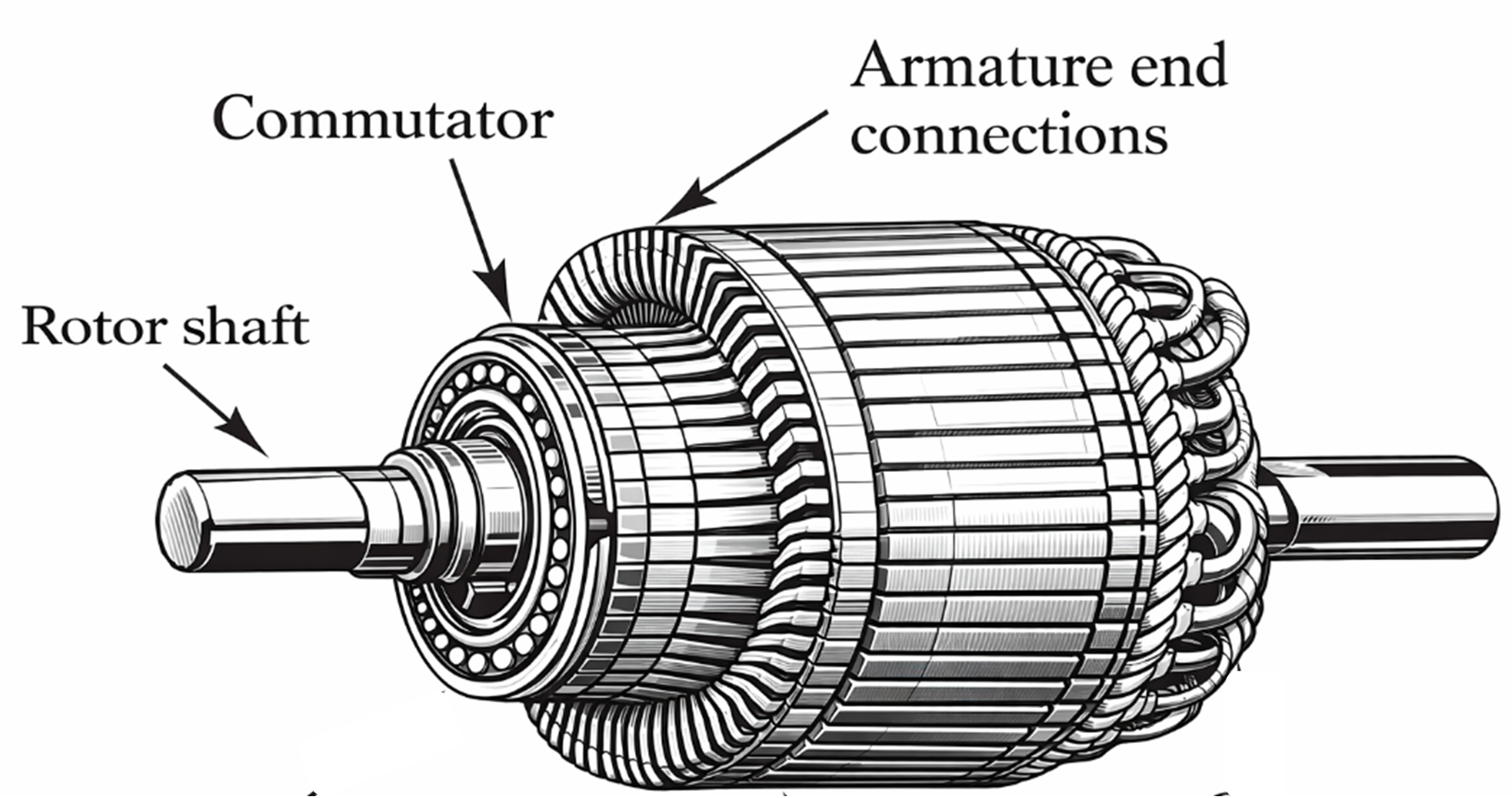
The armature core is made from laminated silicon steel sheets to minimize eddy current losses. It is cylindrical in shape and mounted on the rotor shaft. The outer surface contains multiple slots in which the armature conductors or windings are placed. The windings are connected to the commutator segments.
3. Commutator
The commutator is a key component responsible for converting the induced alternating emf in the armature into unidirectional DC output. It consists of multiple wedge-shaped copper segments insulated from each other using thin layers of mica. Each segment is connected to an armature coil.
During operation, the commutator reverses the connections at precise intervals to maintain correct current direction in the output circuit (in generators) or armature winding (in motors).
4. Brushes
The brushes are made of carbon or graphite and rest on the commutator surface. Their function is to collect current from the commutator (generator mode) or supply current to the armature (motor mode). They also help maintain stable electrical contact during rotation.
5. Rotor Shaft
The rotor shaft supports the armature and rotates along with it. Mechanical power input or output is transmitted through this shaft depending on whether the machine operates as a motor or generator.
Types of Armature Winding
The classification of armature winding depends on how conductors are connected to commutator segments. The two major winding types are:
1. Lap Winding
In lap winding, the armature coils are interconnected such that the number of parallel paths equals the number of poles. If the machine has Z conductors and P poles, then there will be P parallel paths with Z/P conductors in each path. This makes it suitable for low-voltage, high-current applications.
2. Wave Winding
In wave winding, the armature coils are arranged to form only two parallel paths irrespective of the number of poles. Thus each path carries half of the total conductors (Z/2). It is commonly used in high-voltage, low-current machines.
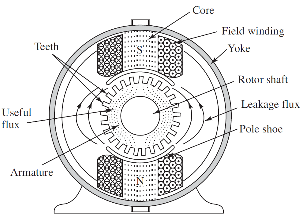
Magnetic Flux Path in a DC Machine
When current flows through the field windings, the pole cores behave like powerful electromagnets. Each pole develops either a north (N) or south (S) polarity, creating alternating magnetic poles around the stator. The flux generated at a north pole travels through the air gap, enters the armature teeth, then passes through the armature core and returns to the opposite pole through the yoke, forming a closed loop.
Only a portion of the flux contributes to energy conversion; this is called the useful or working flux. Some of the flux leaks through nearby paths instead of crossing the air gap, forming leakage flux. Although small, leakage flux slightly reduces efficiency and must be considered during design.
Purpose of Armature Teeth and Slots
The armature surface contains multiple precisely machined slots. These slots hold the armature conductors securely, while the projected portions between slots form the armature teeth. The teeth guide magnetic flux effectively and provide mechanical strength to withstand centrifugal forces at high speed.
The armature is built from thin laminated sheets instead of solid steel. Laminations minimize eddy current losses, which would otherwise cause overheating due to continuously changing flux under rotating poles.
Armature Reaction – Interaction of Fields
When current flows through the armature conductors during operation, they produce their own magnetic field. This armature field interacts with the main field generated by the poles. As a result, the original flux distribution becomes distorted and the neutral axis shifts from its ideal position. This effect is known as armature reaction.
If not compensated, armature reaction may cause:
- Unequal flux density under poles
- Sparking at brushes
- Excess heating
- Reduced efficiency
To counteract it, modern DC machines use interpoles and compensating windings, which restore uniform flux distribution and ensure smooth current reversal during commutation.
Commutation – How AC inside the Armature Becomes DC at Output
Even though the induced emf inside the armature is alternating in nature, the commutator converts it into DC before it reaches the external circuit. As the rotor turns, commutator segments switch coil connections exactly when current direction changes. This ensures that current flowing through the brushes remains unidirectional.
Proper commutation prevents:
- Sparking at brushes
- Heating and carbon erosion
- Electrical noise
- Reduced lifespan of the machine
Torque Production in a DC Motor
Mechanical torque is produced when current-carrying armature conductors experience force inside the magnetic field. According to Fleming’s left-hand rule, each conductor experiences a mechanical push. The combined force acting on all active conductors results in continuous rotation of the rotor.
The value of torque depends on:
- Strength of the magnetic field
- Armature current
- Number of conductors
- Mechanical load
Back EMF in DC Motors
As the armature rotates, it also behaves like a generator and develops an induced emf opposite in direction to the applied supply voltage. This opposing voltage is known as back emf (Eb). It controls armature current automatically and stabilizes motor speed.
When load increases:
- Speed falls
- Back emf reduces
- Armature current increases
- Torque rises
This natural self-regulation makes DC motors highly efficient and responsive.
Losses in DC Machines
Like all electromechanical devices, DC machines experience energy losses such as:
- Copper losses in windings
- Core losses (eddy current & hysteresis)
- Mechanical losses (friction, windage)
- Brush contact losses
Reducing these losses improves performance, output power, and machine lifespan.
Practical Importance of DC Machines
Even though modern AC drives dominate industry today, DC machines remain highly relevant in:
- Research laboratories
- Industrial automation
- Defense and traction
- Electric vehicle learning systems
- Foundries and rolling mills
- Educational training and engineering courses
Their simple construction, strong torque behavior, and controllable characteristics make them indispensable in many fields where precision and reliability are essential.
Advantages of DC Machines
- Simple and rugged construction
- Excellent speed and torque control
- High starting torque capability
- Wide range of operating speeds
- Suitable for traction and industrial drives
- Easy to maintain and repair
Disadvantages of DC Machines
- Presence of commutator and brushes increases maintenance
- More mechanical wear and tear
- Higher manufacturing cost
- Sparking issues at high loads
- Lower efficiency compared to modern AC drives
Applications of DC Machines
- Electric traction systems
- Cranes, hoists and elevators
- Rolling mills and steel industries
- Battery-powered vehicles
- DC power supply systems
- Testing laboratories and research setups
- Control and automation equipment
Conclusion
DC machines continue to remain highly relevant in power conversion, industrial control, and educational fields. Their straightforward construction, superior torque control, and flexible operating characteristics make them crucial in many engineering applications. Whether functioning as a generator or a motor, the same basic structure enables reliable and efficient energy conversion.