Construction of Weston Type Frequency Meter
The construction and connection diagram of the Weston type frequency meter is shown in the Figure 1. It consists of two coils, coil-1 and coil-2 (each divided into two parts) which are placed perpendicular to each other.
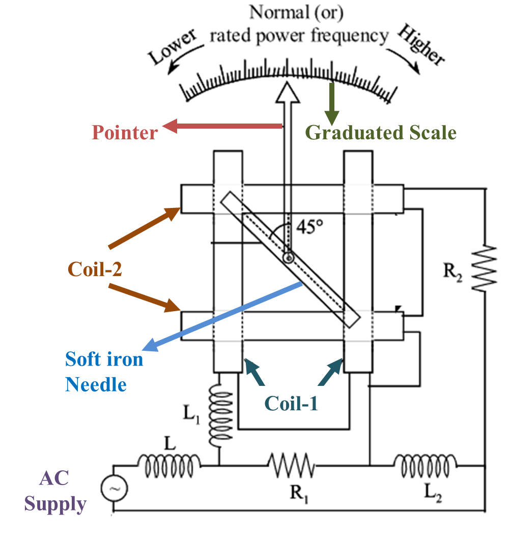
Figure (1): Weston Type Frequency Meter.
At the centre, a needle made up of soft iron material is mounted on a spindle. A pointer is attached to the needle at an angle of 45° and this assembly forms the moving system. The resistance R1 is connected across the series combination of coil-1 and inductance L1. The inductance L2 is connected across the series combination of coil-2 and resistance R2. Both these combinations of R1 and L2 are connected in series and they are connected to the supply through harmonic damping inductor L. This instrument does not have any provision for control device.
Working of Weston Type Frequency Meter
Weston Type Frequency Meter works on the principle of variation in inductive reactance with frequency. At normal or rated supply frequency, the current through both the coils will be equal and the magnetic fields setup by them will be perpendicular to each other. So, the needle takes up a position where both the fields cancels each other. Obviously, the neutral region will be at an angle of 45° from the axis of coil-1 as well as coil-2. Hence the needle rests in that position and the pointer will be at centre of the scale, indicating the normal frequency.
If the supply frequency is less than normal or rated value, then the reactances due to L1 and L2 reduces. This increases the current through coil-1 (as L1 is in series) and reduces through coil-2 (as L2 is in parallel). Hence the field of coil-1 becomes stronger than that of coil-2 and so the needle deflects towards the axis of coil-1 and the pointer indicates the corresponding lower frequency. Similarly, when the supply frequency is higher than that of rated value, then the reactances due to L1 and L2 increases. This reduces the current through coil-1 and increases through coil-2. Hence, the field of coil-2 becomes stronger and so the needle deflects towards the axis of coil-2 indicating higher frequency.