UJT Relaxation Oscillator is a nonlinear oscillator which generates a non-sinusoidal signal such as sawtooth waveforms as output.
Circuit Diagram for UJT Relaxation Oscillator
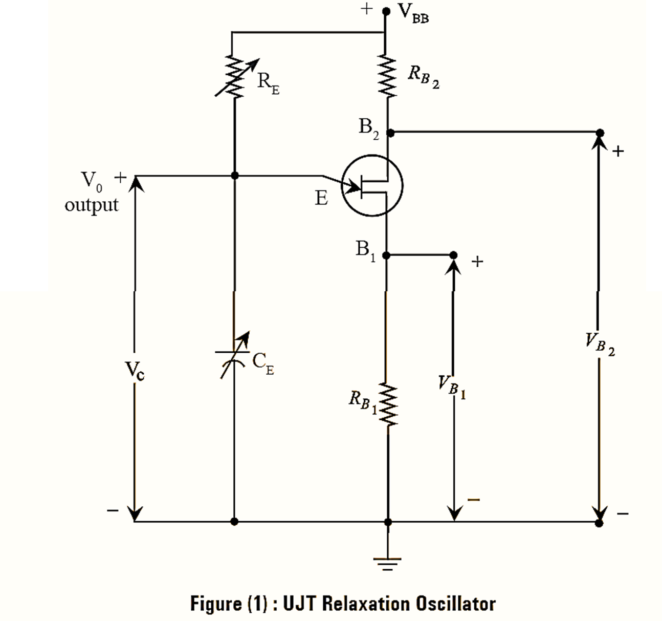
The circuit diagram for UJT Relaxation Oscillator is as illustrated in figure (1). The circuit includes a variable resistor RE and capacitor CE across the emitter terminal. The capacitor, CE charges through the emitter resistor RE when the supply VBB is ON. The capacitor charges to peak value i.e., peak-point voltage VP and turns UJT ON.
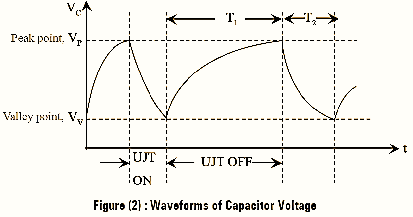
Then, the capacitor discharges through the resistor RB1 and provides negative resistance, due to this UJT acts as relaxation oscillator. UJT conducts till, the voltage across the capacitor reaches to valley point VV and again the process of capacitor charging and discharging repeats. Thus, it provides a sawtooth wave form at its output as shown in figure (2). The base resistance RB1 and RB2 generates spike wave forms. When UJT conducts, the current flows through RB1 results a small potential drop across it, that provides a positive going spike. Similarly, the increase in current across resistor RB2 gives a negative going spike. The variable capacitor, C and resistor, R can be timed to a desired value to attain certain frequency. Since, the time constant depends on these values and is expressed as,
τ = RC
Frequency of Oscillation
The drop across the capacitor, C is given by,
\[{{V}_{C}}={{V}_{BB}}(1-{{e}^{-t}}^{/RC})\]
The time taken for charging capacitor to a peak point voltage is obtained as follows.
\[{{V}_{C}}(\text{ charging })={{V}_{V}}+({{V}_{BB}}-{{V}_{V}})(1-{{e}^{-t}}^{/RC})\]
\[={{V}_{V}}+{{V}_{BB}}(1-{{e}^{-t}}^{/RC})-{{V}_{V}}+{{V}_{V}}{{e}^{-t}}^{/RC}\]
\[={{V}_{BB}}-({{V}_{BB}}-{{V}_{V}}){{e}^{-t}}^{/RC}\]
Since, VC = VP at t = T1,
\[{{V}_{P}}={{V}_{BB}}-({{V}_{BB}}-{{V}_{V}}){{e}^{-{{T}_{1}}}}^{/RC}\]
\[{{V}_{BB}}-{{V}_{P}}=({{V}_{BB}}-{{V}_{V}}){{e}^{-{{T}_{1}}}}^{/RC}\]
\[-\frac{{{T}_{1}}}{{{R}_{C}}}=\text{ ln}\left( \frac{{{V}_{BB}}-{{V}_{P}}}{{{V}_{BB}}-{{V}_{V}}} \right)\]
\[{{T}_{1}}=RC\text{ ln }\left( \frac{{{V}_{BB}}-{{V}_{V}}}{{{V}_{BB}}-{{V}_{P}}} \right)….(1)\]
Similarly, the discharging period T2 given by,
\[{{V}_{C}}={{V}_{P}}{{e}^{-t/RC}}\]
\[\frac{{{V}_{C}}}{{{V}_{P}}}={{e}^{-{{T}_{2}}/RC}}\]
Since, at t = T2, VC = VV, we get.
\[\frac{{{V}_{V}}}{{{V}_{P}}}={{e}^{-{{T}_{2}}/RC}}\]
\[{{T}_{2}}=RC\text{ ln }\left( \frac{{{V}_{P}}}{{{V}_{V}}} \right)….(2)\]
The total time taken for charging and discharging of capacitor is evaluated as,
\[T={{T}_{1}}+{{T}_{2}}\simeq {{T}_{1}}\text{ }\left[ \text{ Since, } {{T}_{1}}>>{{T}_{2}} \right]\]
From equation (l), we get,
\[T=RC\text{ ln }\left( \frac{{{V}_{BB}}-{{V}_{V}}}{{{V}_{BB}}-{{V}_{P}}} \right)\]
Since, VBB >> VV above equation can be written as,
\[T=RC\text{ ln }\left( \frac{{{V}_{BB}}}{{{V}_{BB}}-{{V}_{P}}} \right)\]
\[=RC\text{ ln }\left( \frac{1}{1-\frac{{{V}_{P}}}{{{V}_{BB}}}} \right)\]
Since, VP = ηVBB + VB and VB is forward voltage of diode with a negligible value, T can be obtained as,
\[T=RC\text{ ln }\left( \frac{1}{1-\eta } \right)\]
\[=2.303\text{ lo}{{\text{g}}_{10}}\left( \frac{1}{1-\eta } \right)\]
The oscillating frequency of sawtooth wave is given by, \[{{f}_{o}}=\frac{1}{T}\]
\[{{f}_{o}}=\frac{1}{2.303\text{ RClo}{{\text{g}}_{10}}\left( \frac{1}{1-\eta } \right)}\]