A turbine flow meter is a device used to measure the flow rate of a fluid (liquid or gas) by converting the kinetic energy of the fluid into rotational motion of a turbine. The flow rate is proportional to the rotational speed of the turbine.

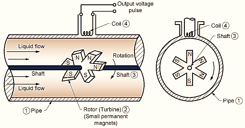
Figure 1: Turbine Flow Meter.
Working Principle of Turbine Flow Meter
The turbine flow meter is based on Faraday’s Law of Electromagnetic Induction. As the liquid flows through the pipe, it rotates the rotor. The rotor’s blades are equipped with permanent magnets, which create a magnetic field.
When fluid flows through the pipe, the rotor starts to rotate due to the kinetic energy of the flowing liquid. The speed of rotation of the rotor is proportional to the flow rate of the liquid.
As the rotor rotates, the magnetic poles (N and S) of the magnets pass near the coil. This induces voltage pulses in the coil.
The frequency of the voltage pulses corresponds to the rotational speed of the rotor. By counting these pulses, the flow rate of the liquid can be determined.
Construction of Turbine Flow Meter
Pipe (1): Through which the liquid or gas flows.
Rotor (Turbine) (2): Inside the pipe, a rotor or turbine with small permanent magnets is mounted on a shaft. The rotor blades are angled to make the turbine rotates as fluid flows through it.
Shaft (3): The rotor is connected to a shaft that holds it in place and allows free rotation.
Coil (4): A magnetic pickup coil is placed outside the pipe. It senses the magnetic field changes caused by the rotating rotor.
Working of Turbine Flow Meter
At the centre of pipe line a shaft is supported in the bearing. Turbine blades NS, NS, NS pairs are fitted on the shaft. Rate of rotation of rotor is proportional to the rate of flow of liquid through the pipe. At the surface of the pipe a coil having no. of turns is fitted firmly. Now rotor blades rotate as fluid flow is impinged on them. Rotor blades are alternately N-pole, S-pole and hence a magnetic field is around the poles.
When the rotor rotates the magnetic field produced by them also rotates. It is a rotating magnetic field. This flux is cut by the number of turns of the coil fitted on the surface of pipe. As per Faraday’s law therefore EMF i.e. voltage is produced in the coil. Value of this voltage depends on the rotational speed of rotor and rotation is due to the flow of liquid.
Voltage ∝ fluid flow rate
The scale is calibrated such that this voltage indicates the fluid flow rate.
Advantages of Turbine Flow Meter
- Better accuracy.
- Allows low pressure drop.
- It provides excellent repeatability and rangeability.
- Low maintenance.
- Easy installation.
- It gives good temperature and pressure ratings.
- Accuracy range is from ± 0.25% to ± 0.50%.
- Repeatability ranging is from ±0.25% to ± 0.02%.
- Available in sizes from 6.25 mm to 60 mm.
- Liquid flow rate from 0.1 to 50,000 gallons/minute.
Disadvantages of Turbine Flow Meter
- Very costly.
- Creates problems for non-lubricating fluids.
Applications of Turbine Flow Meter
- For measurements of liquid, gas.
- Measuring low flow rates.
- In military operations.
- Useful in blending system for petroleum industries.
- Useful in airborne applications for energy fuel and cryogenic (liquid, Oxygen and Nitrogen) flow measurement.