A transformer is a static A.C machine which transfers electrical energy from one circuit to the other circuit without change in frequency.
Working Principle of Transformer
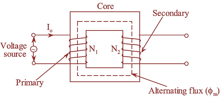
Figure 1: Transformer.
The working principle of transformer is based on mutual induction between two coupled coils. According to this principle a changing flux creates an induced e.m.f in each turn equal to the derivative of the flux so that the total induced e.m.f across N turns is,
\[E=\frac{Nd\phi }{dt}\]
This can be seen in transformer shown in figure 1. Transformer core is wound with two windings having N1 and N2 number of turns. The winding with N1 turns is known as primary as it is fed by alternating voltage source. This voltage source also forms a closed path in the primary. So that alternating current starts flowing through the primary.
Alternating flux set-up by the alternating m.m.f (I0N1), creates an induced e.m.f E1 in the primary. During the path completion of the alternating flux through the core, induced e.m.fs are also created in the winding other than the primary winding. The winding in which e.m.fs are induced mutually is known as secondary winding.
By the principle of electromagnetic induction during this transfer, the voltage level may increase or decrease with a corresponding decrease or increase in current.
Construction (or Parts) of Transformer
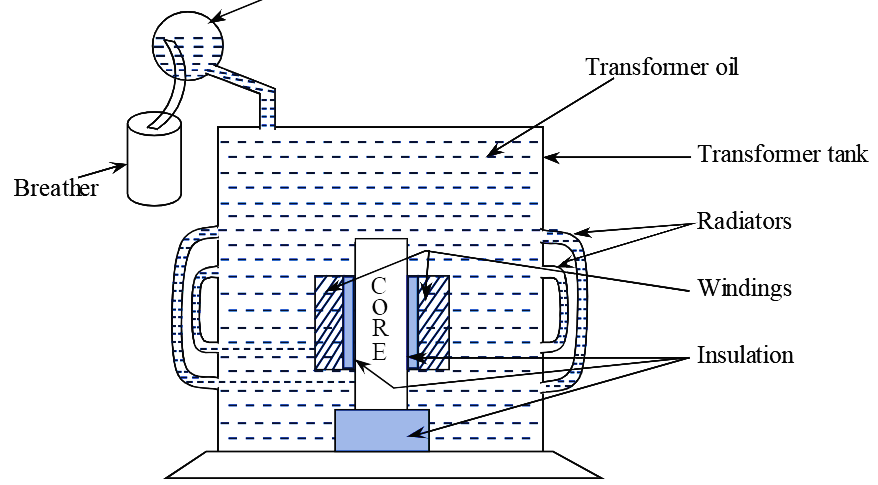
Figure 2: Schematic arrangement of Transformer.
The schematic diagram of a transformer is shown in figure 2. The main components of a transformer are,
- Core
- Windings
- Conservator tank
- Bushings
- Breather
- Radiators
- Transformer oil.
1. Core
The core of a transformer is made up of steel sheet doped with 4% of silicon, which is also called as silicon steel. Thin silicon steel sheets of thickness 0.35 mm to 5 mm depending upon the requirement are cut into particular sizes and shapes and are stocked together to form the magnetic core. Since, the core is cut by the alternating flux produced by the flow of alternating cur-rents, this induces an e.m.f in the core and results in the flow of eddy currents. This eddy current circulates in the core and gives rise to PR loss in the core. To reduce the eddy current loss caused by the flow of eddy current, the core is built-up of laminations.
The purpose of the core is to provide low reluctance path between the two windings, so that the flux caused by one winding will fully link the other coil.
2. Windings
A single phase transformer has two windings. The winding connected to the A.C source is called primary winding and the one connected to load is called secondary’ winding. The alternating voltage whose magnitude is to be changed is applied to primary. The primary and secondary windings consist of a series of turns called coils, which wound round the core. The coils of transformer are of two types. They are,
- Concentric coils and
- Sandwiched coils.
(i) Concentric Coil
Generally, the concentric windings are used in core type transformers. The whole length of the transformer core limb is concentrically wound with the high voltage winding and on high voltage winding, low voltage winding is placed concentrically. The low voltage winding is placed close to the core of a transformer for the reason that the insulation involved is less.
(ii) Sandwiched coils
Sandwiched coils are used in shell type transformers. These type of transformers consist of series of flat coils with a high voltage winding sandwiched between low voltage windings and the low voltage windings occupy the ends to reduce the insulation.
3. Conservator Tank
The oil in the transformer main tank is subjected to expand and contract due to the variations in load current. While undergoing expansion and contraction, the oil is subjected to heat. The function of the conservator tank is to help the oil in the tank to settle down by expansion whenever heavy loads appear. Without a conservator tank, the main tank may burst out because of the high pressures developed inside the tank.
4. Bushings
Connections from the transformer windings are brought out by means of bushings. The function of the bushings is to give proper insulation for the output leads. Bushings are fixed on the transformer tank. Bushings made up of porcelain are available and can be used up to 33 kV. Capacitor and oil filled type of bushings are used for voltages above 33 kV.
5. Breather
The main transformer tank and some portion of the conservator tank are filled with oil. This oil should not be exposed to the atmosphere directly because it may absorb the moisture and dust and may loose its electrical properties within a very short time. i.e., when the temperature changes, the transformer oil expands or contracts and there is a displacement of air. When the transformer gets cool, the level of oil goes down and air is drawn in. This is known as breathing. The air coming in is passed through an apparatus known as breather for the purpose of extracting moisture.
Breather consists of calcium chloride or silica gel by which, moisture in the air is absorbed. Calcium chloride or silica gel is in reddish brown colour but after absorbing the moisture changes to bluish colour. Breather completely prevents the outside atmospheric moisture and dust from coming into contact with oil.
6. Radiators
Thin metal structures are connected around the transformer tank which acts as a heat sink. The function of radiators is to cool the transformer tank gradually.
7. Transformer Oil
It serves the following purposes.
- Provides additional insulation.
- Carries away the heat generated in coils and the core.
- Protects the paper from dust and moisture.
Oil should be free from dust, small water particles and fibres and also from high viscosity. Transformer oil must possess the property of minimum sludge formation after long periods of heating in the presence of oxygen.
Frequently Asked Questions on Transformer
Q1. What happens if D.C supply is applied to the transformer?
Ans1: Transformer is a static device which transforms A.C power from one circuit to another with same frequency. This means it is a pure A.C device, which cannot be operated on D.C.
As the basic requirements to generate e.m.f in any conductor are, conductor itself, magnetic field and the relative motion between conductor and magnetic field, the magnetic field produced by D.C flows uniformly.
Therefore there would not be relative motion between magnetic field and conductor, hence no voltage is induced in secondary winding. Apart from this, the insulation used in transformer is to withstand A.C power, if D.C is used heat dissipated will be high and transformer may burn out. Hence transformer should never be operated on D.C.
Q2. Why transformer rating is in kVA?
Ans2: The copper losses in a transformer depends on current while the iron losses depend on voltage. Therefore, the total losses in a transformer depend on Volt-Ampere (VA) but not on the phase angle between voltage and current i.e., load power factor. Hence, the rating of a transformer is in kVA but not in kW.