Tap changing transformers are transformers equipped with mechanisms (tap changers) to modify the number of turns in the primary or secondary windings. This adjustment changes the voltage ratio, allowing the output voltage to be regulated under varying input or load conditions.
What is Tap Changing Transformer?
A transformer with tappings on the primary or secondary in order to control the voltage is called as a Tap changing transformer. The tappings are the percentage windings equipped to produce the desired amount of voltage. Tap changers are needed due to the following two reasons.
- To stabilize the voltage
- To control the voltage.
Working Principle of Tap Changing Transformer
Tap changing transformer uses the principle of regulating the voltage is based on changing the transformation ratio by altering the number of active tums in one of the winding of transformer.

Figure 1: Tap Changing Transformer.
Tappings can be provided at either primary or secondary winding of transformer as shown in figure. Number of active tums in any winding can be changed by changing it’s tappings. This can be done by the equipment known as tap changer
If secondary active tums (N2) are reduced by the tap changer, then the resultant output voltage (E2) will be reduced or increase in active primary turns (N1) by using tap changer and also results in reduced voltage at the output.
Since,
\[{{E}_{2}}=\frac{{{E}_{1}}{{N}_{2}}}{{{N}_{1}}}\]
Thus,
E2 decreases if N1 increases or E2 decreases if N2 decreases
Similarly, decrease in active primary turns or increase in active secondary turns will result in increased output voltage. It is clear that voltage regulation is achieved with the help of tap changer by changing active tums in one of the windings. The necessity for voltage regulation by the tap changer is due to the following requirements.
- To change the secondary voltage to the desired value.
- To match the transformer output voltage with the consumer terminal voltage.
- To keep the output voltage constant though the input voltage is varying.
- To control the real and reactive power flow in the network.
- To provide the neutral point.
Types of Tap Changing Transformer
- Off-Load Tap-Changing Transformers (OLTC): Tap changes are made only when the transformer is de-energized and suitable for systems with infrequent voltage adjustment needs.
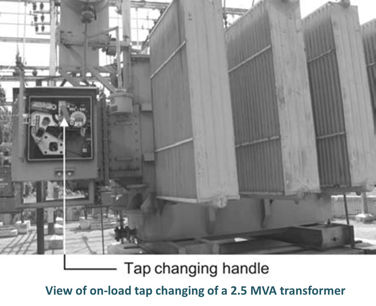
- On-Load Tap-Changing Transformers (OLTC): Tap changes can be made while the transformer is energized and supplying load and equipped with additional components like diverter switches, resistors, or reactors to avoid circuit interruptions.
Off Load Tap Changing Transformer
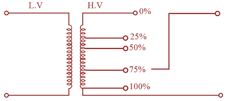
Figure 1: Off-Load Tap Changing Transformer.
Off-load tap charger is used to change the transformer turns ratio. In this type of tap changer, the tapping is changed when the transformer is de-energized i.e., in order to change the tap settings the transformer has to be switched-off and then settings can be changed. The generalized circuit of an offload tap changer is as shown in figure. The taps are usually provided on the H. V side of the transformer. Here different settings are provided, i.e., 25%, 50%, 75%, and 100% . Depending on the required voltage, the load can be connected between the appropriate taps. Suppose the given transformer has the ratings, 500/1000 V Now if the load requirement is 500 V then the terminals should be connected between 0% and 50% and if the load requirement is 750 V, then the load terminals should be connected between 0% and 75%. Hence, a smooth control of voltage is possible depending on the requirements. Off-load tap changers are used for seasonal voltage variations which does not come frequently.
On Load Tap Changing Transformer
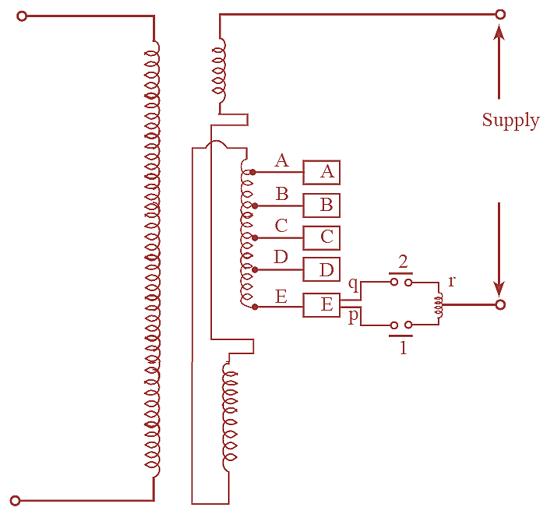
Figure 1: On-Load Tap Changing Transformer.
The main draw back of off-load tap changer is that, it can’t be operated by keeping the transformer energized i.e., the transformer has to be disconnected in order to change the settings. However, this can be overcome by employing on-load tap changer, where the settings can be changed when the transformer is in operating condition, this ensures reliability.
However care must be taken to see that short circuit of any part of tapped winding is prevented. Also, alternate path must be provided for load current using alternate circuit during the process of tap changing in main circuit otherwise huge sparking will occur and may damage the transformer. The generalized circuit of on-load tap changer is as shown in figure. The tappings are provided on the H. V side. A, B, C, D and E are the studs connected to different tappings, r is a centre tapped reactor connected through switches 1 and 2 to the stud terminals by using movable terminals q and p. The function of the reactor is to prevent the short circuit of the tapped windings. The above figure shows the arrangement of tap changer for full supply voltage when both the terminals p and q are in contact with stud E. Now in order to have a change in voltage, the terminals must move to desired stud i.e., D, C, B, A. To do this, first of all the switch 2 must be opened and q must be moved to desired stud. Now, close switch 2 and open switch 1 and move terminal p also to the desired stud.
Therefore, while changing the terminals p and q to the desired position. One switch is kept open and other is closed so that there is no interruption in supply The on-load tap changer is used for voltage variations which come frequently.
Advantages of Tap Changing Transformer
- Voltage Regulation: They maintain a stable output voltage despite fluctuations in input voltage or load.
- Improved System Performance: Reduces voltage drops and ensures proper operation of connected equipment.
- Flexibility: Provides adjustable voltage settings to adapt to different operational requirements.
- Energy Efficiency: Minimizes energy losses by maintaining voltage at optimal levels.
- Load Adaptability: Ensures stable voltage for varying load conditions.
Disadvantages of Tap Changing Transformer
- Cost: On-load tap-changing transformers (OLTC) are expensive due to their complex mechanisms.
- Maintenance: Regular maintenance is required for tap changers, especially OLTC, to ensure reliability.
- Limited Switching: Off load tap changers require the transformer to be de-energized for adjustments, leading to downtime.
- Complexity: OLTC mechanisms are mechanically and electrically complex, increasing the risk of failure.
Applications of Tap Changing Transformer
- Power Distribution Systems: Regulate voltage to ensure efficient power delivery in grids.
- Industrial Applications: Provide stable voltage for machines and equipment.
- Renewable Energy Systems: Regulate output voltage from renewable sources like wind and solar farms.
- Substations: Ensure voltage levels meet transmission and distribution requirements.
- Railway Electrification: Maintain voltage consistency for railway power supplies.
- High-Rise Buildings: Stabilize voltage for electrical systems in large buildings.
In summary, tap-changing transformers are essential components in power systems, enabling voltage regulation to ensure system stability, efficiency, and adaptability to varying load and supply conditions.