Synchroscope instrument is used for synchronization process. i.e. Connecting 3 phase alternator for parallel operation.
Necessity of Synchroscope
In power system, the 3 phase alternators, transformers are connected in parallel with system. When 3 phase alternator are connected to the line or system, the correct instant of connecting it to the system is important. That instant is synchronising instant. To detect this correct instant of synchronising, synchroscope is used.
Working and Construction of Synchroscope
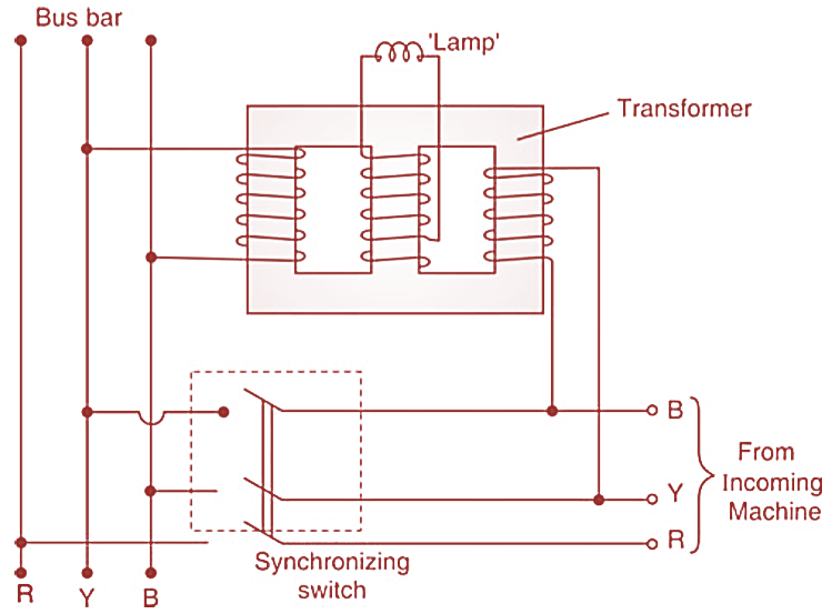
Figure 1: Synchroscope Connection Diagram.
It consists of a 3-Limbed transformer as shown in Figure 1. On the central limb a lamp is connected across winding. On the first limb winding is connected to bus-bars and on the third limb the winding is connected to the incoming machine. The windings when connected will produce the fluxes which are combined and pass through central limb. The resultant flux will be more if bus bar voltage and incoming machine voltage are in phase. So the emf induced in the winding of the central limb will be maximum and the lamp will glow with maximum brightness. If the two voltages are 180º apart then resultant flux will be zero and EMF in the central limb coil will be zero and lamp will be dark. If the frequency of the incoming machine is different than the bus bar frequency then the lamp will be alternately bright and dark and will flicker. The correct instant of synchronizing the incoming machine with the bus bar will be when the flickering is minimum and lamp shows maximum brightness.

Figure 2: Synchroscope Construction (Dynamometer type instrument).
In this type (see Figure 1) of synchroscope the drawback is that, it does not show whether the machine is too fast or too slow. This drawback is overcome by introducing dynamometer type instrument in the circuit as shown in Figure 2.
This is a part of Weston Synchroscope. The construction is similar to dynamometer type instrument with fixed coil in two sections (FF) and a moving coil (H) placed between them. When incoming machine voltage is in phase with bus bar voltage, the current Il and I2 in the coils will be in quadrature and hence no torque on the instrument.
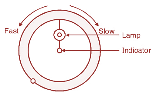
Figure 3: Synchroscope Indicator.
The pointer will be vertical. The lamp will glow very bright. The scale of the instrument is of opal-glass and it is marked slow or fast on either side of the centre position. The lamp is placed behind the pointer and the scale. Thus when the pointer is at centre zero position, the synchronizing switch is made on, which is the correct instant of synchronizing. If the incoming machine is slow or fast, (i.e. two frequencies are not same) then the pointer oscillates about the centre zero position pointing the incoming machine slow or fast. Due to the small inductance ‘L’ in the F.F. coil circuit we get exact quadrature relation between Il and I2.
Controlling torque is not provided this is because, the moving coils are fixed at right angles to each other. The moving system gets adjusted because of interaction of two fluxes produced by both fixed and moving coils and thereby equilibrium condition is obtained without any external controlling force.
Applications of Synchroscope
Synchroscope is useful in the process of synchronizing (connecting in parallel) an incoming machine with the bus- bars.