It is possible to apply more than one input signal to an inverting amplifier. This circuit will then add all these input signals to produce their addition at the output. Such a circuit will then be called as an adder or a summing amplifier.
Types of Summing Amplifier (Adder) Using Op-Amp
Depending on the polarity or sign of the output voltage the adder circuits can be classified into two categories as :
- Inverting adder and
- Non-inverting adder.
Inverting Adder or Inverting Summing Amplifier
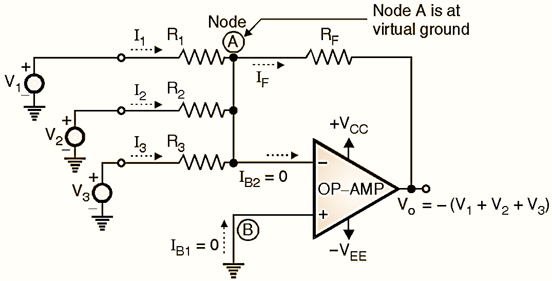
Figure 1: Summing Amplifier.
Fig. 1 shows the “inverting summing amplifier” configuration with three inputs V1, V2, and V3. Depending on the relation between the feedback resistor RF and the three input resistances R1, R2, and R3 we can use the same circuit shown in Fig. 1 as a summing amplifier, scaling amplifier or averaging amplifier. V1, V2 and V3 are three input signals applied simultaneously to the inverting terminal of the OP-AMP through resistors R1, R2 and R3 respectively. V1, V2, and V3 are measured with respect to ground. RF is the feedback resistor, connected between the output terminal and the inverting input terminal of OP-AMP. The non-inverting input terminal is connected to ground. So the configuration of Fig. 1 is basically an inverting amplifier with three inputs. Let the currents through the resistors R1, R2 and R3 be I1, I2 and I3 respectively. For the analysis of this circuit, we assume that the OP-AMP is ideal. Hence its input resistance is Ri = ∞. Therefore the currents IB1 and IB2 are zero. In addition to this, Node A is at virtual ground potential.
Expression for the output voltage :
Apply KCL at node A of Fig. 1 to write,
\[{{I}_{1}}+{{I}_{2}}+{{I}_{3}}={{I}_{B2}}+{{I}_{F}}\]
But as Ri of the OP-AMP is ideally infinite, IB2 = 0, and VA = VB = 0 due to virtual ground concept.
Hence,
\[{{I}_{1}}+{{I}_{2}}+{{I}_{3}}={{I}_{F}}\]
On the input side,
\[{{I}_{1}}=\frac{{{V}_{1}}-{{V}_{A}}}{{{R}_{1}}}=\frac{{{V}_{1}}}{{{R}_{1}}}\text{ as }{{V}_{A}}=0\]
Similarly,
\[{{I}_{2}}=\frac{{{V}_{2}}-{{V}_{A}}}{{{R}_{2}}}=\frac{{{V}_{2}}}{{{R}_{2}}}\]
\[{{I}_{3}}=\frac{{{V}_{3}}-{{V}_{A}}}{{{R}_{3}}}=\frac{{{V}_{o}}}{-{{R}_{3}}}\]
And on the output side,
\[{{I}_{F}}=\frac{{{V}_{A}}-{{V}_{o}}}{{{R}_{F}}}=-\frac{{{V}_{o}}}{-{{R}_{F}}}….(1)\]
Substituting these values in Equation (1) we get,
\[\frac{{{V}_{1}}}{{{R}_{1}}}+\frac{{{V}_{2}}}{{{R}_{2}}}+\frac{{{V}_{3}}}{{{R}_{3}}}=-\frac{{{V}_{o}}}{{{R}_{F}}}\]
Or,
\[{{V}_{o}}=-\left[ \frac{{{R}_{F}}}{{{R}_{1}}}{{V}_{1}}+\frac{{{R}_{F}}}{{{R}_{2}}}{{V}_{2}}+\frac{{{R}_{F}}}{{{R}_{3}}}{{V}_{3}} \right]\]
In Equation (1) if we substitute RF = R1 = R2 = R3 = R then we get,
\[{{V}_{o}}=-({{V}_{1}}+{{V}_{2}}+{{V}_{3}})\]
Thus output voltage is the negative sum of the input voltage. Therefore this circuit is called as “Inverting adder” or “Inverting summing amplifier”. Similarly, we can add any number of inputs.