Strain gauge is a resistive type transducer which converts change in mechanical displacement into a proportional change in resistance. It is the most commonly used method of displacement measurement.
Working Principle of Strain Gauge
Their working principle is based on piezo-resistive effect. The piezo-resistive effect states that if a metal conductor is stretched or compressed, its length and diameter changes. Therefore its resistance also gets changed. Similarly the resistance of a metal conductor changes when it is strained.
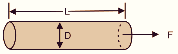
Fig. 1 shows an unstrained wire of elastic material with length L, Diameter: D and Area of cross-section = A.
\[R=\rho \frac{L}{A}=\rho \frac{L}{(\pi /4){{D}^{2}}}\]
\[R=\rho \frac{L}{A}=\rho \frac{L}{\left( \frac{\pi }{4} \right){{D}^{2}}}\]
Where,
ρ = Resistivity of the wire in Ω – m
If this wire of elastic material (Strain Gauge) is subjected to tension, its length increases and diameter reduces. These changes in the dimensions due to applied force are shown in Fig. 2.
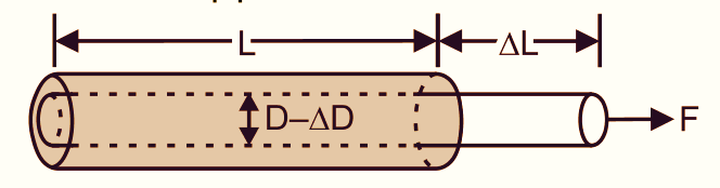
Let the change in length = ΔL and change in diameter = ΔD. To find the change in resistance (ΔR) due to applied force we use Poisson’s ratio.
\[\text{Using Poisson ratio (}\mu \text{) = }\frac{(\Delta D/D)}{(\Delta L/L)}\]
But,
\[\frac{\Delta L}{L}=\sigma =\text{ Strain}\]
Therefore,
\[\Delta D=\mu .\sigma .D\]
Thus the change in resistance is given by ΔR = Rσ (1+2µ).
From the above equation, we can conclude that the resistance of the wire increases due the applied force. The gauge factor (G) of a strain gauge is defined as the unit change in resistance per unit change in length. Therefore,
\[G\text{= }\frac{(\Delta R/R)}{(\Delta L/L)}\] (Ranges from 1.5 to 1.7)
Types of Strain Gauge
The two types of strain gauges as
- Bonded Strain Gauge
- Unbonded Strain Gauge
Bonded Strain Gauge
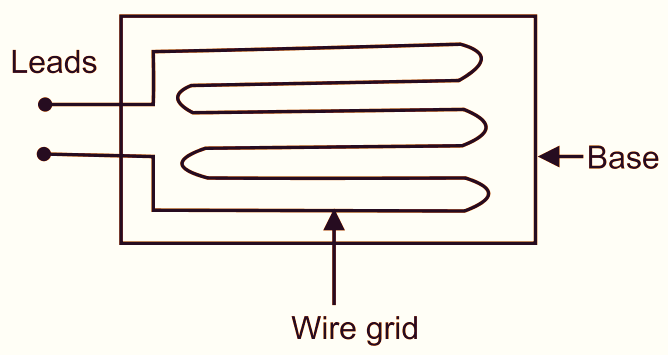
Fig. 3: Bonded Type Strain Gauge.
A bonded strain gauge consists of a grid of fine wire which is fixed on a base of a thin paper sheet as shown in Fig. 3. The paper sheet is bonded with an adhesive to the spot under measurement. When force is applied to the surface, to which the strain gauge is bonded, the resistance of the grid wire changes due to the change in length and diameter of the wire. This change in the resistance can be measured by connecting the strain gauge in one of the arms of the Wheatstone bridge that generates equivalent voltage. The bonded strain gauge is useful only for measuring very small displacements. To measure large displacements, the strain gauge is bonded to a flexible element like cantilever beam. The displacement can then be measured at the end of the cantilever beam.
Unbonded Strain Gauge
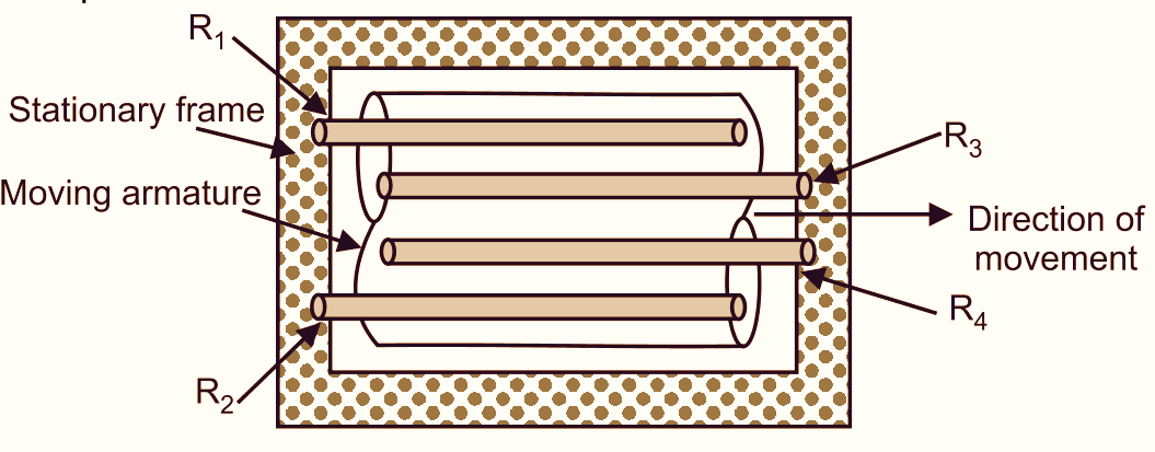
Fig. 4: Unbonded Type Strain Gauge.
As shown in Fig. 4, an unbonded strain gauge is constructed by fitting the gauge wire on a stationary frame having a movable armature fixed at the centre. The armature can be moved only in one direction and its travel is limited by four strain gauge wires. If an external force is applied to the strain gauge or the armature is moved, the gauge wire gets stretched showing a proportional change in its resistance value which can be measured with the Wheatstone bridge. The output voltage of the Wheatstone bridge can be calibrated according to displacement of the armature.
Advantages of Strain Gauge
- High accuracy and reliability.
- Small size and easy to use.
Disadvantages of Strain Gauge
- High cost.
- The changes in temperature may affect the output.