Servomotors are also known as “control motors”. They are generally used in feedback control systems as output actuators. There are two types of servomotors. They are,
- AC servomotors and
- D.C servomotors.
AC Servomotor

The principle of operation of A.C servomotor is similar to that of three-phase induction motor. AC servomotors are generally two-phase squirrel cage induction type motors. The stator has two distributed windings. One is the control winding and the other is the reference winding. These two windings are displaced from each other by 90º as shown in above figure. The voltage applied to the control winding will be 90º out of phase with respect to the voltage applied to the reference winding. The current in the control winding will set up a flux and this flux will be 90º out of phase to the flux set up by the current in the reference winding. Thus, a resultant rotating magnetic flux is setup in the air gap, which sweeps over the stationary rotor. Due to this rotating flux, an e.m.f is induced in the rotor, which in turn produces a circulating current in the rotor. This circulating current in the rotor will now set up a flux (rotor flux) which interacts with the resultant flux produced by the stator and thus a torque is developed on the rotor. The effect of this torque is that the rotor starts rotating in the same direction as the rotating magnetic flux.
Applications of AC Servo Motor
- AC servo meters are used for low power applications.
- These motors are widely used in radar, process control systems, robotics, servo mechanisms, computers and machine tools etc.
- These are also used in self balancing recorders, AC position control systems, tracking and guidance systems.
DC Servo Motor

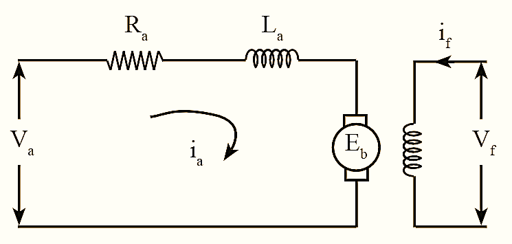
DC motors which are used in servo systems are called DC servo motors. DC servo motor is essentially an ordinary D.C motor except with few variations in its constructional features. These are used when quick response to control signals and high starting torque is required. The figure shows the layout of DC servo motor.
Working Principle of DC Servo Motor
When an electric current flows through the armature winding, the magnetic field is induced in it. This induced field opposes the field, which is set up by the permanent magnets. The difference in magnetic field produces a torque on the rotor. The torque produced by the rotor will be constant throughout the rotation, as the field strength depends on the function of current. The torque of the D.C servo motor is given as,
\[{{T}_{m}}(t)={{k}_{m}}{{I}_{a}}(t)\]
Where,
Tm — Torque produced
Ia – Armature current
km – Motor’s torque constant.
Applications of DC Servo Motor
- D.C servomotors are used for high power applications.
- These motors are widely used in instruments, tape drives, printers, robot system, air craft control systems etc.
- These are also used in electromechanical actuators, process controllers and disk drive.
Difference between AC servomotor and DC servomotor
|
AC Servomotor |
DC Servomotor |
| AC servomotors are best suited for low power applications and has a power output of about \(\frac{1}{2}\) W to 100 W. | DC servomotors are generally used for large power applications and deliver high power output. |
| The effciency of these motors is very less i.e., 5 to 20%. | The efficiency of these motors is high. |
| It requires less maintenance due to the absence of commutators. | Due to the presence of commutator frequent maintenance is needed. |
| Radio frequency noise is not produced. | Radio frequency noise is produced due to brushes. |
| The operation of this servomotor is relatively stable and smooth. | The operation of this servomotor is noisy.
|
| AC amplifiers used in these motors have no drift. | Amplifiers used in these motors have a drift. |
| Stability problems are less. | Stability problems are more. |