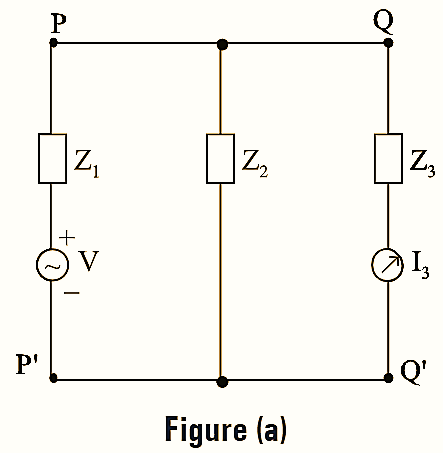
“In a linear, passive and bilateral single source network, the ratio of response to the excitation is constant even though the source is interchanged from the input terminals to the output terminals”.

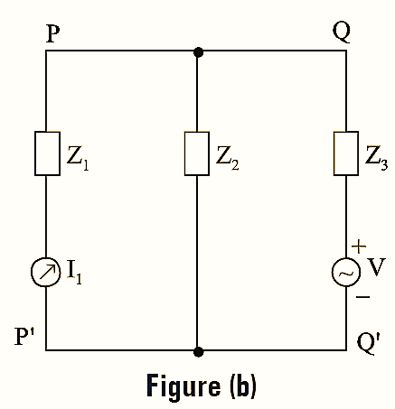
Suppose that the application of voltage ‘ V ‘ across PP’ produces current is through the branch QQ’ having impedance Z3. Then, the ratio of the response to excitation is given by,
\[\frac{R}{E}=\frac{{{I}_{3}}}{V}…(1)\]

Now, the positions of source and response are interchanged. The voltage source is connected across the terminals QQ’ and it produces current response I1 through the branch PP’ having impedance Z1 as shown in the figure (b). Now, the ratio of the response to the excitation is given by,
\[\frac{R}{E}=\frac{{{I}_{1}}}{V}…(2)\]
According to reciprocity theorem, the ratio of response to the excitation is constant in both cases.
Hence,
Equation (1) = Equation (2)
\[\frac{{{I}_{3}}}{V}=\frac{{{I}_{1}}}{V}=\frac{I}{V}\left( Constant \right)\] \[As \left[ i.e,{{I}_{3}}={{I}_{1}} \right]\]

Consider the network shown in figure (1). Suppose application of voltage V across AA’ produces current I through BB’. Now, if the positions of source and responses are interchanged by connecting the voltage source across BB’, the resultant current I will flow through terminals AA’. According to reciprocity theorem, the ratio of response to excitation is same in both the cases. The reciprocity theorem is not valid for a network with two sources.
i.e,\[\frac{I}{V}=\text{ Constant }\left( \text{In both the cases} \right)\]
Reciprocity Theorem Example

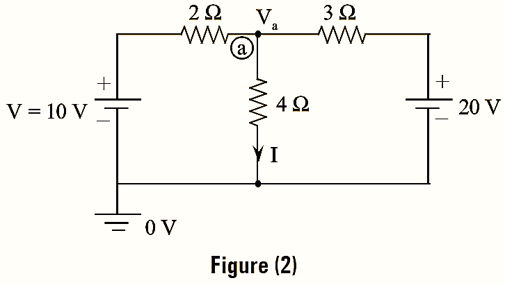
Consider the network shown in figure (2). Let 10 V voltage source be the excitation (or input) and current I be the response (or output). By applying KCL at node ‘a’, we get,
\[\frac{{{V}_{a}}-10}{2}+\frac{{{V}_{a}}}{4}+\frac{{{V}_{a}}-20}{30}=0\]
\[{{V}_{a}}\left( \frac{1}{2}+\frac{1}{3}+\frac{1}{4} \right)-\frac{10}{2}-\frac{20}{3}=0\]
\[{{V}_{a}}\times \frac{13}{12}=\frac{35}{3}\]
\[{{V}_{a}}=\frac{35}{3}\times \frac{12}{13}=\frac{140}{13}\text{V}\]
\[I=\frac{{{V}_{a}}}{4}=\frac{140}{13\times 4}=\frac{35}{13}\text{A}\]
The ratio of response to the excitation is,
\[\frac{I}{V}=\frac{35}{13}\times \frac{1}{10}=\frac{7}{26}…(3)\]

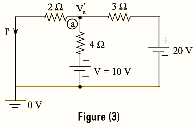
When the input and output terminals are interchanged, the circuit until be modified as shown in figure (3).
\[\frac{{{{{V}’}}_{a}}}{2}+\frac{{{{{V}’}}_{a}}-10}{4}+\frac{{{{{V}’}}_{a}}-20}{3}=0\]
\[{{{V}’}_{a}}\left( \frac{1}{2}+\frac{1}{3}+\frac{1}{4} \right)=\frac{10}{2}+\frac{20}{3}\]
\[{{{V}’}_{a}}\times \frac{13}{12}=\frac{55}{6}\]
\[{{{V}’}_{a}}=\frac{55}{6}\times \frac{12}{13}=\frac{100}{13}\text{V}\]
\[{{{I}’}_{a}}=\frac{{{{{V}’}}_{a}}}{2}=\frac{100}{13\times 2}=\frac{55}{13}\text{A}\]
The ratio of response to the excitation is,
\[\frac{{{I}’}}{V}=\frac{55}{13}\times \frac{1}{10}\]
\[=\frac{11}{26}…(4)\]
As equations (3) and (4) are not equal it can be said that the reciprocity theorem is invalid for networks with two or more sources.