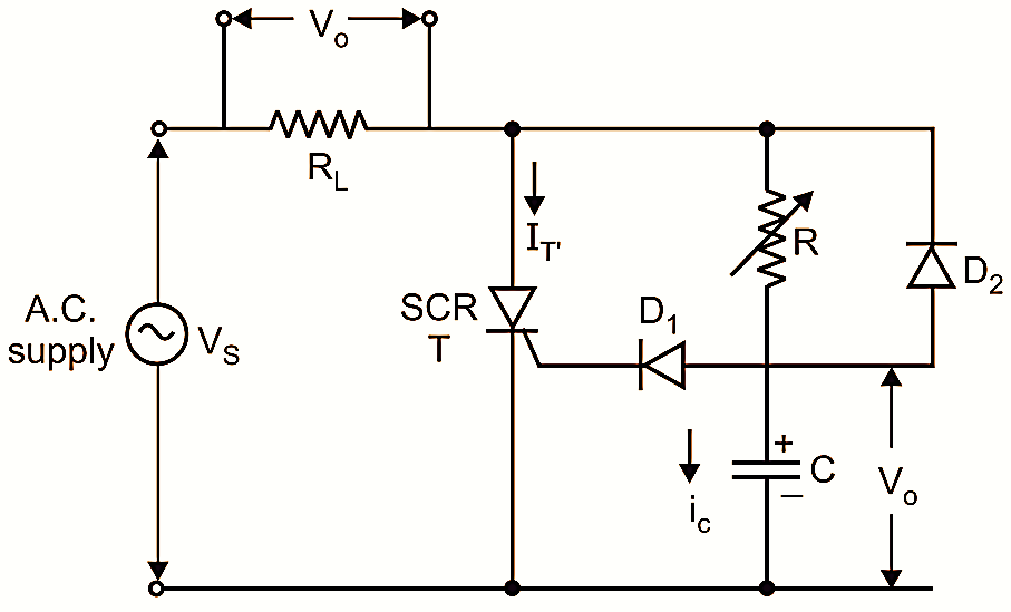
Figure 1: RC Triggering of SCR.
The limited range of firing angle only upto 90° in the resistor trigger method of an SCR can be overcome by using RC trigger circuit of SCR. The limited range of firing angle can be increased from 90° to 180°, if the gate circuit of an SCR is supplied by a voltage that is shifted in its phase relationship to the anode voltage in such a manner that the positive gate current sufficient to trigger the SCR can be delayed beyond the peak of the anode voltage.
Circuit Diagram of RC Triggering of SCR
Fig. 1 shows the circuit diagram of an RC trigger for an SCR. The a.c. voltage is applied between the anode and cathode of an SCR. The variable resistor R is used to limit the gate current. It also controls the firing angle of an SCR. The diode D1 is a blocking diode which is used as a preventive safeguard to the gate-cathode junction of an SCR from getting damaged in the negative half cycle of the applied a.c. voltage. The capacitor C is used to apply the reverse voltage and improve the firing angle from 90° to 180°. The diode D2 is used to reset the capacitor C to the peak of the negative half cycle of the supply voltage.
Principle of Operation of RC Triggering of SCR
The a.c. voltage is applied between the anode and the cathode of an SCR T. Consider that the SCR is in the forward blocking (OFF) state. In the positive half cycle of the applied a.c. voltage, the capacitor C is initially charged through the variable resistor R upto the peak value of the applied voltage, as the diode D2 is now reverse biased. The charging rate of the capacitor C can be controlled by the variable resistor R. The voltage across the capacitor C will be the time integral of current Ic admitted to it by a variable resistor R. When the voltage VC across the capacitor C is sufficient, the diode D1 allows the gate current. Depending on the voltage across the capacitor C and if the gate current at is sufficient, the SCR turns ON. The resistor R can control the firing angle. In the negative half cycle of the applied a.c. voltage, the capacitor C is charged upto the negative peak value through the diode D2, thus resetting it for the next charging cycle. Now the diode D1 is reverse biased and it is known as a blocking diode. It is used as a preventive safeguard against the reverse breakdown of the gate-cathode junction of an SCR during the negative half cycle. The diode D1 must be rated to support at least the peak of the supply voltage VSC. The diode D2 resets the capacitor C to the peak of the negative cycle. The diode D1 must be rated to support at least the peak of the supply voltage VSC. The diode D2 resets the capacitor C to the peak of the negative supply voltage VS and hence it must be rated to withstand the voltage at least 2VS, if there is a possibility of opening of the resistor R. The main function of the capacitor C is to shift the phase of the anode voltage so that a positive gate current can be supplied after the peak of the anode voltage. By varying the resistor R, the firing angle can be controlled from 0° to 180°.
Waveforms of RC Triggering of SCR
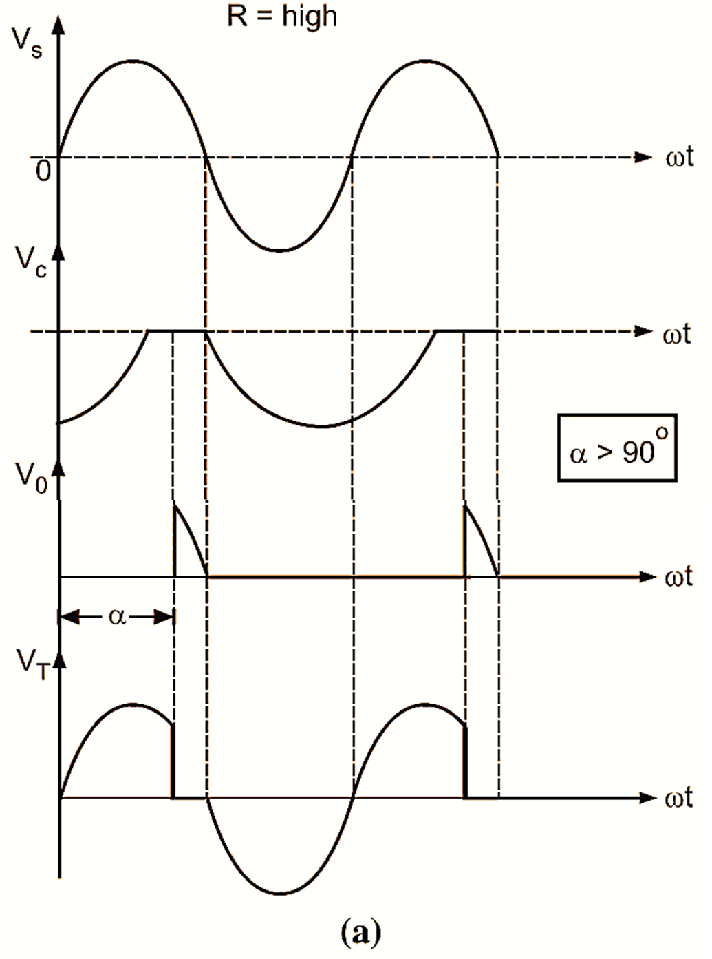
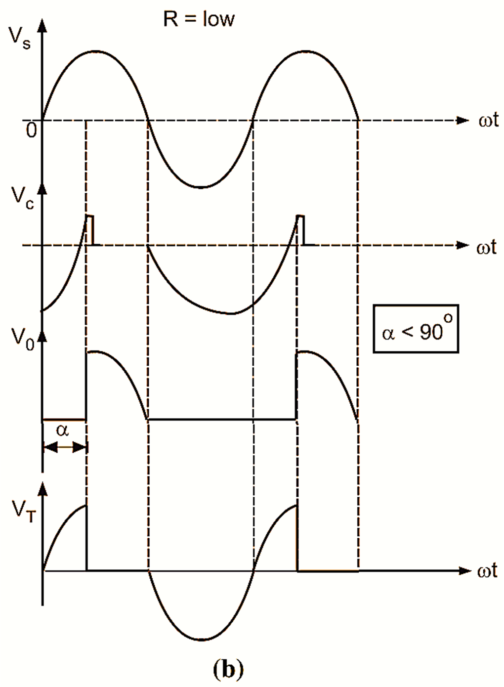
Figure 2: Waveforms for RC half-wave trigger circuit for two different values of R.
Fig. 2 shows voltage waveforms for RC trigger circuit for different values of R. When SCR turns ON, its ON-state voltage drop is approximately 1 V. This low voltage across SCR during turn-ON period keeps capacitor C discharged in positive half cycle until negative voltage cycle across C appears. When value of resistance R is high, the time taken by capacitor C to charge to required gate voltage is more because charging current is low. Therefore, firing angle α is more and output voltage Vo is less. Thus the output voltage Vo is inversely proportional to the firing angle α.
Advantages of RC Triggering of SCR
The RC trigger circuit has the following advantages :
- It is the most simple and economical circuit.
- It has a firing angle ranging from 0° to 180°.
- It is less sensitive to temperature variations.
Disadvantages of RC Triggering of SCR
The disadvantages of RC trigger circuit are as given below :
- It is not suitable for feedback control system because the control signal is a.c. and the feedback is through mechanical components.
- It suffers from limited response time.
- It does not have repeatability over a temperature range.