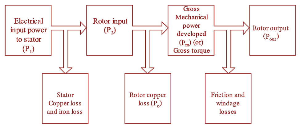
Figure 1: Power Flow Diagram of Induction Motor.
Induction motor takes electrical power as input and converts it into useful mechanical power output.
The electrical power is given as input to the stator,
\[{{P}_{1}}=\sqrt{3}{{V}_{L}}{{I}_{L}}\cos \phi \]
This input power (P1) is given to the stator winding, some of the input power is lost as heat in copper coils and in iron coils and the remaining power is delivered to rotor winding as input (P2).
Input to the rotor is given as,
\[{{P}_{2}}={{P}_{1}}-\text{Losses in stator}\]
Similarly in rotor, when it rotates, heat is developed in its conductors and some of the input power is lost as heat. The remaining power is converted into mechanical power. This mechanical power is known as gross mechanical power (Pm).
\[\text{Gross mechanical power }{{P}_{m}}={{P}_{2}}-{{P}_{c}}\]
Where, Pc is the rotor losses.
Now, this gross mechanical power is supplied to the load connected to the shaft. But again some part of mechanical power is lost as friction and windage losses and the remaining power is delivered to the shaft as output power.
Output power
\[{{P}_{out}}={{P}_{m}}-(\text{Friction + Windage losses})\]
Relationship between Rotor Input, Rotor Copper Loss and Mechanical Power Developed
Let,
\[\text{Rotor input = }{{T}_{g}}\times 2\pi {{N}_{s}}…(1)\]
\[\text{Rotor gross output = }{{T}_{g}}\times 2\pi N…(2)\]
Subtracting equation (2) from equation (1), we get,
Rotor copper loss = Rotor input – Rotor gross output
\[\text{Rotor copper loss = }{{T}_{g}}\times 2\pi {{N}_{s}}\]
\[-\text{ }{{T}_{g}}\times 2\pi N\]
\[\text{Rotor copper loss = }{{T}_{g}}2\pi ({{N}_{s}}-N)\]
Dividing both the sides by rotor input we have,
\[\frac{\text{Rotor copper loss}}{\text{Rotor input}}=\frac{{{T}_{g}}2\pi ({{N}_{s}}-N)}{{{T}_{g}}2\pi {{N}_{s}}}\]
\[\frac{\text{Rotor copper loss}}{\text{Rotor input}}=\frac{{{N}_{s}}-N}{{{N}_{s}}}=s\]
Thus,
\[\frac{\text{Rotor copper loss}}{\text{Rotor input}}=s\]
\[\text{Rotor input}=\frac{\text{Rotor copper loss}}{s}\]
\[\text{Rotor copper loss}=s\times \text{Rotor input}\]
\[{{P}_{c}}=s\times {{P}_{2}}\]
The rotor copper loss is slip times the rotor input.
Relationship between Rotor Input and Rotor Gross Output
We know that,
Rotor gross output = Rotor input – Rotor copper loss
\[{{P}_{m}}={{P}_{2}}-{{P}_{c}}\]
\[{{P}_{m}}=({{P}_{2}}-s{{P}_{2}})\text{ }\left[ {{P}_{c}}=s{{P}_{2}} \right]\]
\[{{P}_{m}}=(1-s){{P}_{2}}\]
Therefore, rotor gross output is (1 — s) times the rotor input.
Hence, from equation (6) and equation (7) the ratio can be expressed as,
\[{{P}_{2}}:{{P}_{c}}:{{P}_{m}}={{P}_{2}}:s{{P}_{2}}:(1-s){{P}_{2}}\]
\[=1:s:(1-s)\]
Therefore in an Induction motor,
\[{{P}_{2}}:{{P}_{c}}:{{P}_{m}}=1:s:(1-s)\]