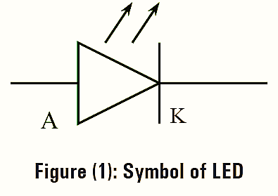
The light-emitting diode (LED) is a light-sensitive diode that emits light when it is forward-biased. Figure (1) shows the symbol of LED.
Working Principle of Light Emitting Diode (LED)
When a free electron from the higher energy level gets recombined with the holes, emits light or photon energy. Here, in case of LEDs, the supply of higher level electrons is provided by the battery.
Construction of Light Emitting Diode (LED)
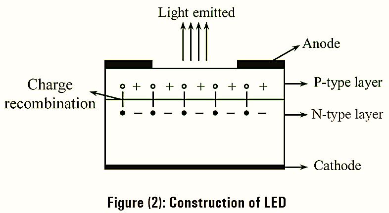
Figure (2) illustrates the cross-sectional view of light emitting diode are the semiconductor materials used for construction of LED. A N-type epitaxial layer is formed on the substrate and P-type layer is deposited on it by the process of diffusion. The carrier recombination process occurs in P-type layer, so P-type layer is kept as the uppermost layer for emission of light.
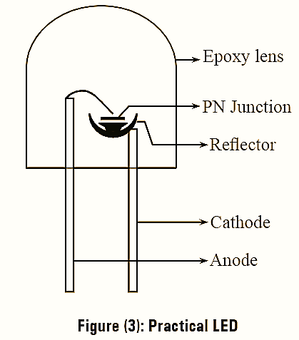
The metallic anode connection is provided such that the light freely escapes from the surface. A gold film is laid to the bottom of substrate such that maximum light is reflected to the surface of device and to establish cathode connection. Practical view of LED is as shown in figure (3). The PN junction is placed on the cup shaped reflector which is connected to anode and cathode by using wires. The whole device is placed in dome shaped epoxy lens.
Working of Light Emitting Diode (LED)
When the PN junction is forward biased, the process of carrier recombination occurs at the junction. An electron crossing from n-type layer recombine with holes on the p-type layer. Free electrons have higher energy levels than holes and some of this energy is dissipated in the form of heat and light during recombination process.
Characteristics of Light Emitting Diode (LED)
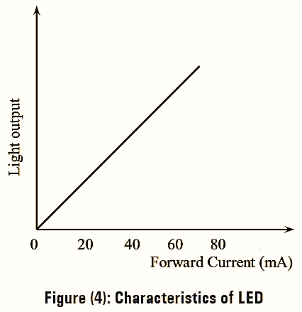
Figure (4) illustrates the typical characteristics of LED. When diode is forward biased, the current flowing through diode increases. As the current increases, the intensity of the light emitting from LED also increases. The following table gives information regarding colored lights produced by various materials.
| Mixture | Color |
| GaAs | Infrared red radiation, Invisible |
| GaP | Red (or) Green |
| GaAsP | Red or Yellow |
Applications of Light Emitting Diode (LED)
- Digital watches
- Optical communication system
- Microprocessor systems
- Digital computers
- Calculators
- Multimeters.
Efficiency of Light Emitting Diode (LED)
The efficiency of a LED depends on the number of injected excess electrons with the emission of the photons. The excess of electrons combines radiatively or non-radiatively. In radiative recombination, the amount of energy emitted from the photon is equal to the band gap.
The ratio of radiative recombination rate to the total recombination rate is defined as the internal quantum efficiency. In the active region, the internal quantum efficiency is the fraction of the electron hole pairs that recombine radiatively.
\[{{\eta }_{{int}}}=\frac{{{R}_{r}}}{{{R}_{r}}+{{R}_{nr}}}\]
Where,
ηint — Internal quantum efficiency
Rr – Radiative recombination rate
Rnr – Non-radiative recombination rate.
The radiative recombination lifetime is \({{\tau }_{r}}=\frac{n}{{{R}_{r}}}\) the non-radiative recombination life time is \({{\tau }_{nr}}=\frac{n}{{{R}_{nr}}}\) equation (1) can be written as,
\[{{\eta }_{{int}}}=\frac{\frac{n}{{{\tau }_{r}}}}{\frac{n}{{{\tau }_{r}}}+\frac{n}{{{\tau }_{nr}}}}….(1)\]
\[{{\eta }_{{int}}}=\frac{\frac{n}{{{\tau }_{r}}}}{\frac{n}{{{\tau }_{r}}}+\frac{n}{{{\tau }_{nr}}}}=\frac{\frac{n}{{{\tau }_{r}}}}{\frac{n}{{{\tau }_{r}}}\left[ 1+\frac{n}{{{\tau }_{nr}}} \right]}\]
\[=\frac{1}{1+\frac{{{\tau }_{r}}}{{{\tau }_{nr}}}}=\frac{{{\tau }_{nr}}}{{{\tau }_{nr}}+{{\tau }_{r}}}\]
\[{{\eta }_{{int}}}=\frac{\tau }{{{\tau }_{r}}}\]
Where,
\[\frac{1}{\tau }=\frac{1}{{{\tau }_{r}}}+\frac{1}{{{\tau }_{nr}}}\]
Where,
τ – bulk recombination rate.
If the amount of current ‘I’ is introduced into LED, then the total number of recombination’s per second is given as,
\[{{R}_{r}}+{{R}_{nr}}=\frac{1}{q}….(2)\]
Substituting equation (2) in equation (1), we get,
\[{{\eta }_{{int}}}=\frac{{{R}_{r}}}{\frac{1}{q}}\]
\[{{\eta }_{{int}}}=\frac{{{R}_{r}}q}{I}\]
The equation, ηint represents the radiative efficiency. The internal quantum efficiency increases with decrease in density of non-radiative recombination sites in band gap. This can be expressed mathematically as,
\[{{\eta }_{i}}=\gamma {{\eta }_{{int}}}\]
Here, ‘γ’ is injection effciency and is defined as the ratio of electron current to the total current in LED i.e., sum of electron, hole and recombination currents.