A constant voltage transformer (CVT) works on ferro-resonant principle. The variation in the primary flux with an unsaturated iron core does not affect the secondary flux with saturated iron core. Thus, the secondary induced voltage remains relatively independent of the voltage impressed upon the primary winding.
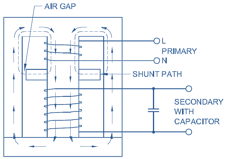
Fig. 1: Constant Voltage Transformer (CVT).
Construction & Working of Constant Voltage Transformer (CVT)
In an ordinary transformer, the primary and secondary coils are closely coupled. Any change in primary voltage is directly transferred to the secondary in the ratio of the number of turns. In a CVT, the primary and secondary coils are loosely coupled. These are wound on separate sections of the transformer core as in Fig 1. In between the coils, a separate shunt path is provided for the flux to flow but an air gap is provided in the shunt path. A capacitor is provided in parallel with the secondary. Now imagine what will happen when voltage is applied to the primary. Starting from zero, if the voltage increases slowly, initially, all the flux generated by the primary voltage will pass through the lower half of the transformer core because the air gap in the shunt path will prevent it from taking this path. This is shown by bold arrows in Fig 1. As a result, the rise in secondary voltage is proportional to the primary. But as voltage in the secondary coil rises, at a certain point the impedance of the coil will become equal to the impedance of the capacitor, i.e.
\[{{X}_{L}}={{X}_{C}}\]
or
\[2\pi fL=\frac{1}{2\pi fC}\]
This is the condition of resonance, and at this point a high current will flow in the LC circuit. This high current will result in a sudden rise of voltage across the secondary (Fig 1), and the core in this section of the transformer will saturate.
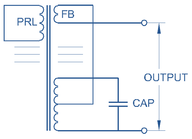
Fig. 1: Constant Voltage Transformer (CVT) with feedback winding.
Once the core gets saturated, it prevents the entry of further flux coming from the primary side. Therefore, any increase in flux due to increase in primary voltage has to take an alternate shunt path as in Fig 1. Hence, very little increase in the secondary voltage takes place. This little increase can also be nullified by a feedback-FB winding connected as in Fig 2. The output winding can be separated from the capacitor circuit if the voltage required is low or tappings can be taken out of the capacitor.
Applications of Constant Voltage Transformer (CVT)
CVT may not be suitable for an instrument in which SCR power supply is used or an inductor or a capacitor is coming in the AC circuit or a motor drawing a heavy in-rush current is used inside the instrument. But it is suitable for electronic machines such as TVs, computers, FAX machines etc.