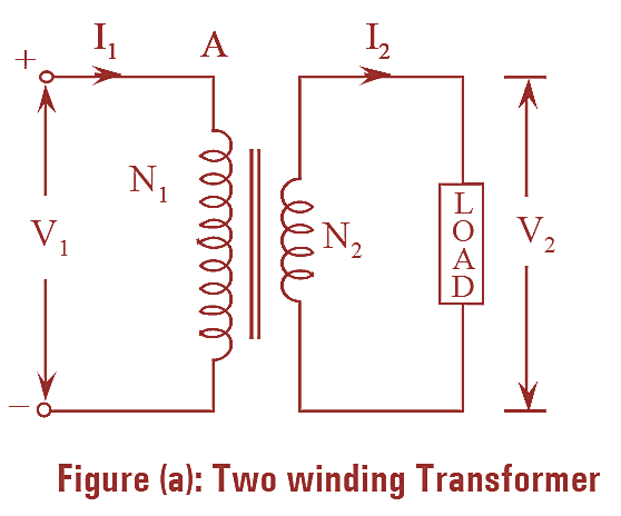
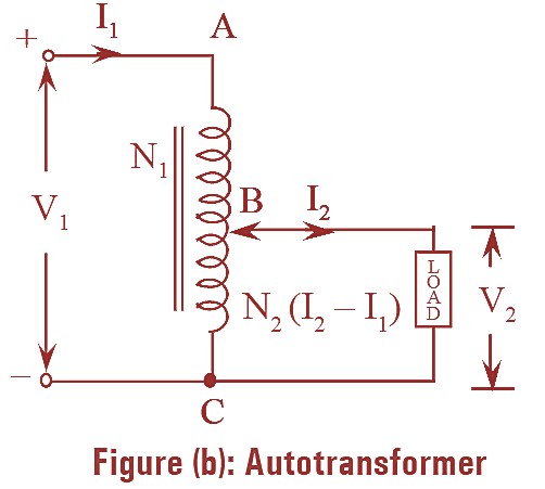
Unlike two winding transformer, an auto-transformer contains only one winding. This single winding serves the purpose of both primary as well as secondary. As this transformer employs only one winding, it uses less copper. Hence it is cheaper and more efficient. The principle of operation of an auto-transformer is same as that of two winding transformer the only difference is the primary and secondary are not electrically separated. The transformation ratio of an auto-transformer is around unity.


Types of Autotrnasformer
There are two types of auto-transformers. They are,
- Step-up auto-transformer
- Step-down auto-transformer.
Construction of Autotransformer
Even though the working principle of two winding transformer and an auto-transformer is same but power transfer in both the transformers is somewhat different. In a two winding transformer the power transfer is purely inductive whereas in case of auto-transformer, the power transfer from primary to secondary winding is both inductive and conductive. In an auto-transformer the power transfer is inductive because of the mutual induction and is conductive because both the windings i.e., primary and secondary are electrically in contact with each other.
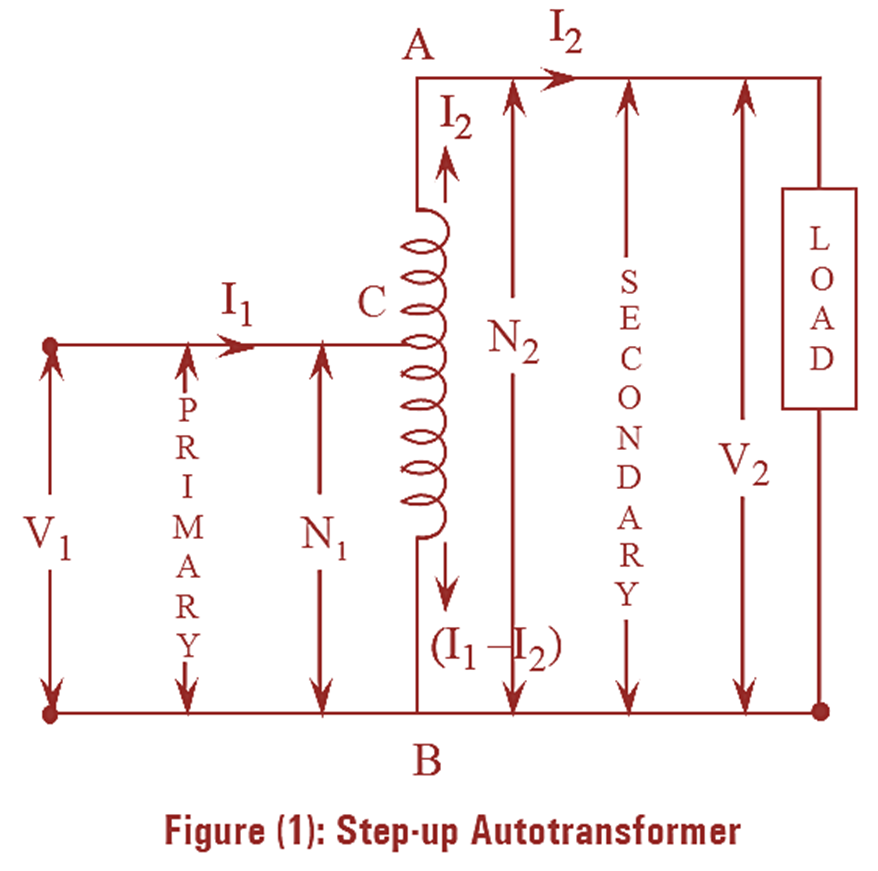
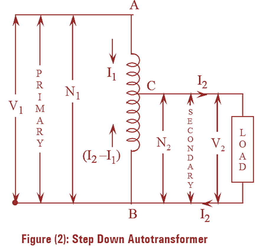
Both step-up auto-transformer and step-down auto-transformer along with direction of flow of currents are shown in figures (l) and (2) respectively. In step-up transformer, the winding from section BC is the primary winding and the winding of section AB is the secondary winding. Hence primary winding BC is a part of secondary winding AB. Therefore, the voltage at secondary is more than the primary voltage and the transformer acts as step-up transformer. Also the condition N2 > N1 satisfies in this transformer. In figure (2) the arrangement of step-down transformer is shown where the entire winding AB is the primary winding and BC acts as the secondary winding. Therefore, secondary winding is a part of primary winding and the transformer acts as step-down transformer. For this case (N1 > N2) and (V1 > V2).
Saving of Copper in Autotransformer


For any winding, copper’s weight is proportional to the area of cross-section and length of the conductors. But it is known that the area and length of the copper winding are in turn proportional to the current and number of turns respectively. Hence it can be concluded that the weight of the copper used for winding is proportional to the product of current and number of turns.
Rating of two types of transformers is identical i.e., both the transformers have equal voltage ratio \(\left( \frac{{{V}_{1}}}{{{V}_{2}}} \right)\), same input and output, maximum flux density and area of core are assumed to be equal.
Weight of copper ∝ Current in winding × Number of turns of winding ∝ IN
Weight of copper in two winding transformer,
wT ∝ (Copper weight of primary + Copper weight of secondary)
\\(\)
And also,
Weight of copper in auto-transformer,
wA ∝ (Copper weight of AC + Copper weight of BC)
\\(\)
Now, taking the ratio of two weights, we get,
\[\frac{{{w}_{T}}}{{{w}_{A}}}=\frac{{{I}_{1}}{{N}_{1}}+{{I}_{2}}{{N}_{2}}}{{{I}_{1}}({{N}_{1}}-{{N}_{2}})+({{I}_{2}}-{{I}_{1}}){{N}_{2}}}\]
\[\frac{{{w}_{T}}}{{{w}_{A}}}=\frac{{{I}_{1}}{{N}_{1}}+{{I}_{2}}{{N}_{2}}}{{{I}_{1}}{{N}_{1}}-{{I}_{1}}{{N}_{2}}+{{I}_{2}}{{N}_{2}}-{{I}_{1}}{{N}_{2}}}\]
\[\frac{{{w}_{T}}}{{{w}_{A}}}=\frac{{{I}_{1}}{{N}_{1}}+{{I}_{2}}{{N}_{2}}}{{{I}_{1}}{{N}_{1}}+{{I}_{2}}{{N}_{2}}-2{{I}_{1}}{{N}_{2}}}\]
\[\frac{{{w}_{T}}}{{{w}_{A}}}=\frac{{{I}_{1}}{{N}_{1}}\left[ \frac{{{N}_{1}}}{{{N}_{2}}}+\frac{{{I}_{2}}}{{{I}_{1}}} \right]}{{{I}_{1}}{{N}_{1}}\left[ \frac{{{N}_{1}}}{{{N}_{2}}}+\frac{{{I}_{2}}}{{{I}_{1}}}-2 \right]}\]
We know that,
\[\frac{{{N}_{1}}}{{{N}_{2}}}=\frac{{{I}_{2}}}{{{I}_{1}}}=\frac{1}{K}\]
\[\frac{{{w}_{T}}}{{{w}_{A}}}=\frac{\frac{1}{K}+\frac{1}{K}}{\left( \frac{1}{K}+\frac{1}{K}-2 \right)}\]
\[\frac{{{w}_{T}}}{{{w}_{A}}}=\frac{\frac{2}{K}}{\frac{2-2K}{K}}\]
\[\frac{{{w}_{T}}}{{{w}_{A}}}=\frac{2}{2(1-K)}\]
\[\frac{{{w}_{T}}}{{{w}_{A}}}=\frac{1}{(1-K)}\]
\[{{w}_{T}}(1-K)={{w}_{A}}\]
\[{{w}_{A}}={{w}_{T}}(1-K)\]
The above equation is the weight of copper in auto-transformer when compared to two winding transformer. Thus,
Saving in copper = Copper weight in two winding transformer – Copper weight in auto-transformer
\[={{w}_{T}}-{{w}_{A}}\]
\[={{w}_{T}}-{{w}_{T}}(1-K)\]
\[={{w}_{T}}-{{w}_{T}}+K{{w}_{T}}\]
\[\text{Saving in copper = }K{{w}_{T}}\]
The above saving is for step down auto-transformer.
Similarly for step-up auto-transformer,
\[\text{Saving in copper = }\frac{1}{K}{{w}_{T}}\]
Advantages of Autotransformer
- High volt-ampere rating can be transferred.
- Voltage variation is smooth and continuous.
- Amount of copper required is less.
- Higher voltage regulation due to less resistance and leakage reactance.
- Efficiency is more.
- It is economical due to its small size.
Applications of Autotransformer
- Autotransformers are used as starter for securely starting the machines like induction motor and synchronous motors.
- These are used as boosters to provide a small boost to a distribution cable to compensate the voltage drop.
- These are also used as furnace transformers for providing required supply to the furnaces.
- These are used as inter connecting transformers in 132 kV/330 kV systems.
- These are also used as variac.
- These are used in various control systems and home appliances.