The reciprocal of impedance \(\left( \frac{I}{Z} \right)\) is known as admittance and its symbol is Y. The unit in which it is measured is siemens (abbreviation, S) which is the admittance of the circuit whose impedance is one ohm.
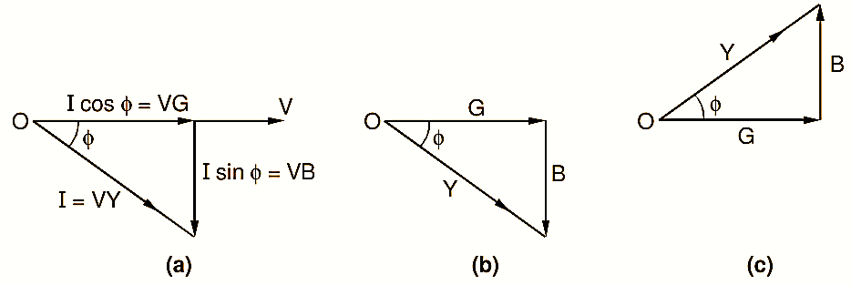
Figure 1: Admittance, conductance, susceptance.
The concept of admittance simplifies the analysis of parallel a.c. circuits to a large extent. Now, consider the case of a simple circuit containing a resistance R and an inductive reactance X (Fig. 1). Let the current drawn by a circuit be I amperes at the phase angle of when connected across the supply of V volts. Then,
\[I=\frac{V}{Z}=V.Y\]
Further, the active component of the current in the circuit is given by,
\[I\cos \phi =\frac{V}{Z}\times \frac{R}{Z}=V.\frac{R}{{{Z}^{2}}}=V.G\]
Where, the quantity G which is the ratio of resistance to the square of the impedance is known as the conductance of the circuit (in the special case when X = 0, then G = 1/R).
Also, the reactive component of the current in the circuit is given by,
\[I\sin \phi =\frac{V}{Z}\times \frac{X}{Z}=V.\frac{X}{{{Z}^{2}}}=V.B\]
The quantity B which is the ratio of reactance to the square of impedance is known as susceptance of the circuit. The unit of the conductance as well as susceptance is again the siemens. Fig. 1 (a) shows the phasor diagram taking the voltage as a reference quantity.
By dividing each side of the current triangle by V, a similar triangle as shown in Fig. 1 (b) can be obtained. As sides of this triangle represent the conductance, susceptance and admittance of the circuit, it is known as admittance triangle. If the circuit has resistance and capacitive reactance in series, then the current leads the voltage and in that case, the admittance triangle is as shown in Fig. 1 (c).
From the admittance triangle, we have the following relationships :
\[G=Y\cos \phi ,\text{ }B=Y\sin \phi ,\text{ }Y=\sqrt{{{G}^{2}}+{{B}^{2}}}\]
And,
\[\tan \phi =\frac{B}{G}\]
It should be remembered that the capacitive susceptance is always considered as positive and inductive susceptance as negative. This will obviously be clear from the corresponding admittance triangles.
APPLICATION OF ADMITTANCE METHOD TO PARALLEL CIRCUITS
Consider the general parallel circuit consisting of three branches shown in Fig. 2 (a).
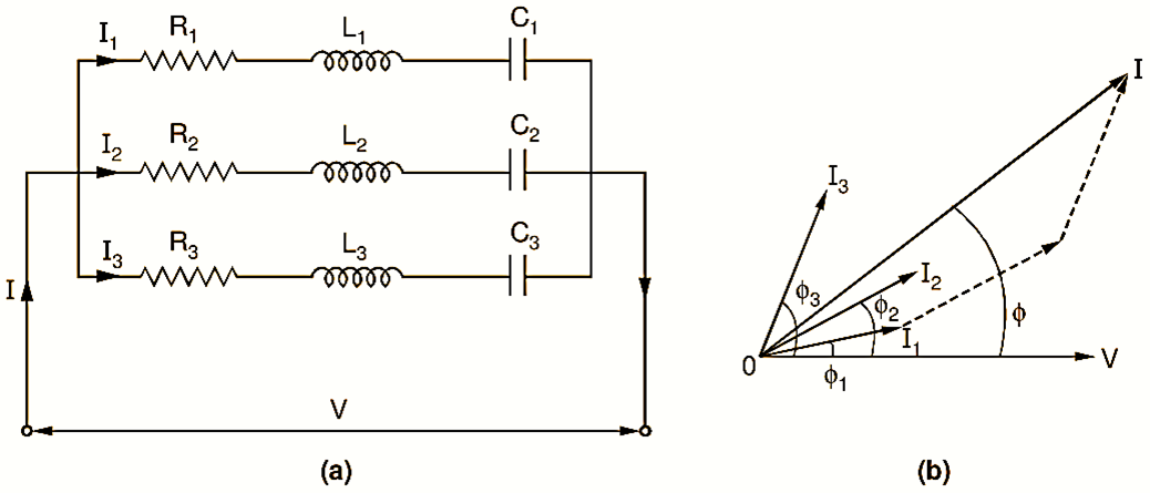
Figure 2: (a) Circuit containing impedances in parallel, (b) Phasor diagram.
Let V be the applied voltage, I the total circuit current and let I1, I2 and I3 be the branch currents. These branch currents will differ in phase with respect to the applied voltage. Let the phase difference between V and the branch currents I1, I2 and I3 be ϕ1, ϕ2 and ϕ3 respectively, the values of which are obtained from reactance and resistance of each branch. e.g.
\[\tan {{\phi }_{1}}=\frac{\left( \omega {{L}_{1}}-\frac{1}{\omega {{C}_{1}}} \right)}{{{R}_{1}}}\]
Fig. 2 (b) shows the phasor diagram for the given circuit in which V is considered as reference quantity. The total current is the phasor addition of all the branch currents. Hence, from the phasor diagram,
\[{{I}^{2}}={{({{I}_{1}}\cos {{\phi }_{1}}+{{I}_{2}}\cos {{\phi }_{2}}+{{I}_{3}}\cos {{\phi }_{3}})}^{2}}\]
\[+{{({{I}_{1}}\sin {{\phi }_{1}}+{{I}_{2}}\sin {{\phi }_{2}}+{{I}_{3}}\sin {{\phi }_{3}})}^{2}}\]
\[={{(V{{G}_{1}}+V{{G}_{2}}+V{{G}_{3}})}^{2}}\]
\[+{{(V{{B}_{1}}+V{{B}_{2}}+V{{B}_{3}})}^{2}}\]
Where,
\[{{G}_{1}}=\frac{{{R}_{1}}}{Z_{1}^{2}},\text{ }{{G}_{2}}=\frac{{{R}_{2}}}{Z_{2}^{2}}\text{, }{{G}_{3}}=\frac{{{R}_{3}}}{Z_{3}^{2}}\]
\[{{B}_{1}}=\frac{{{X}_{1}}}{Z_{1}^{2}},\text{ }{{B}_{2}}=\frac{{{X}_{2}}}{Z_{2}^{2}}\text{, }{{B}_{3}}=\frac{{{X}_{3}}}{Z_{3}^{2}}\]
Here, the branch reactances X1, X2 and X3 are obviously,
\[{{X}_{1}}=\omega {{L}_{1}}-\frac{1}{\omega {{C}_{1}}},\text{ }{{X}_{2}}=\omega {{L}_{2}}-\frac{1}{\omega {{C}_{2}}}\]
\[\text{ and }{{X}_{3}}=\omega {{L}_{3}}-\frac{1}{\omega {{C}_{3}}}\]
Hence, the total admittance, of the whole circuit is given by
\[Y=\frac{I}{V}\]
\[=\sqrt{{{({{G}_{1}}+{{G}_{2}}+{{G}_{3}})}^{2}}+{{({{B}_{1}}+{{B}_{2}}+{{B}_{3}})}^{2}}}\]
\[=\sqrt{{{G}^{2}}+{{B}^{2}}}….(1)\]
And,
\[\tan \phi =\frac{{{({{B}_{1}}+{{B}_{2}}+{{B}_{3}})}^{2}}}{{{({{G}_{1}}+{{G}_{2}}+{{G}_{3}})}^{2}}}=\frac{B}{G}\]
Where,
\[G={{G}_{1}}+{{G}_{2}}+{{G}_{3}}\text{ and }B={{B}_{1}}+{{B}_{2}}+{{B}_{3}}\]
Thus, total conductance of a parallel circuit can be found by merely adding the branch conductances. Similarly, its total susceptance can be found by algebraically adding the individual susceptance of different branches. If Y1, Y2 and Y3 are admittances of the different branches, then, Equation (1) clearly shows that the total admittance of the parallel circuit is given by their phasor addition i.e.
\[\overline{Y}={{\overline{Y}}_{1}}+{{\overline{Y}}_{2}}+{{\overline{Y}}_{3}}\text{ }\]
It should be remembered that similar to impedance, admittance is always treated as a phasor.