A DC generator is the most commonly used separately excited generator, used for electroplating and battery charging. A separately excited generator is one in which the magnetic field is excited from an external DC source. The DC source may be a DC generator or a battery or a metal rectifier connected to an AC supply. Generally, a potential divider is connected across the DC source, and the required DC voltage is supplied to the field as shown in Fig 1.
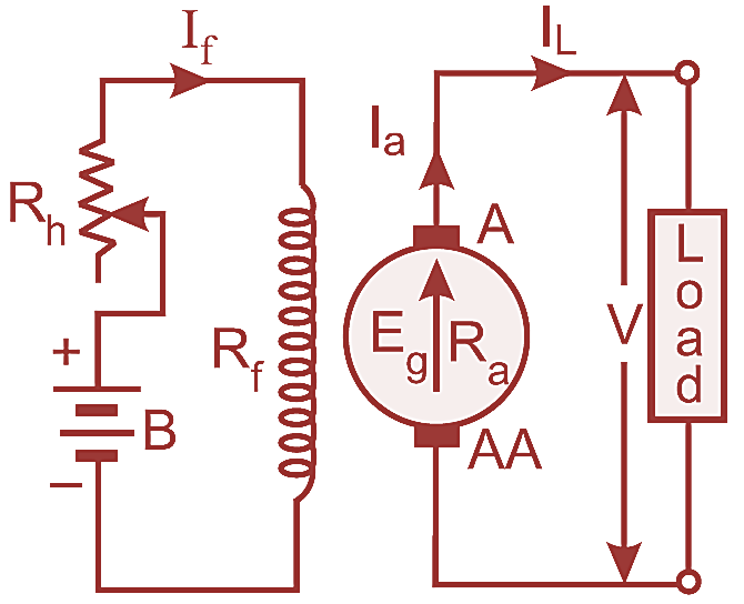
Fig. 1: Separately Excited DC Generator Circuit diagram.
An ammeter is connected in the field circuit to measure the field current. The shaft of the generator is coupled to a prime mover. (Not shown in Fig 1)
Magnetisation Characteristic of a Separately Excited DC Generator:
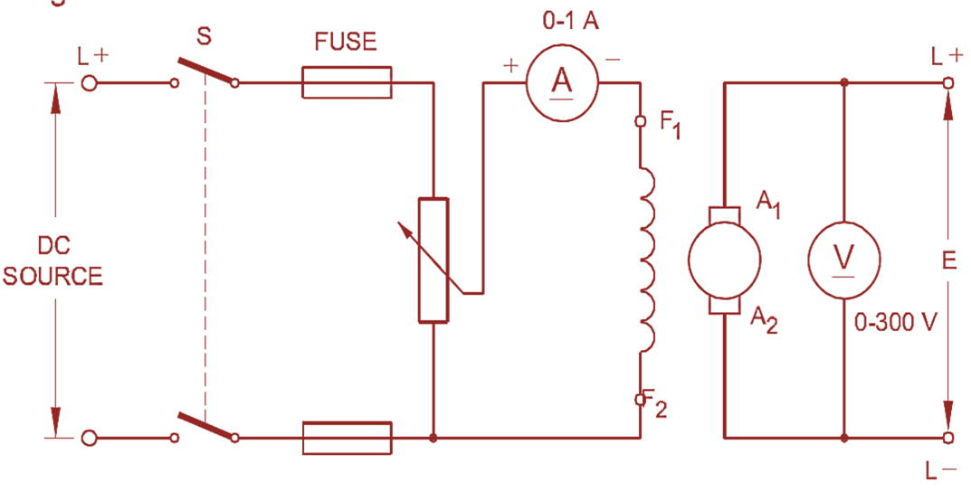
Fig. 2: Separately Excited DC Generator Circuit diagram for Characteristics
This characteristic gives the relation between the field flux and the induced voltage in a generator. However, it is difficult to measure the field flux, and, hence, the field current is taken instead of the field flux. The characteristic curve is drawn by keeping the field current in the `X axis and the induced emf in the `Y axis. To draw the characteristic curve, the connections are made as shown in Fig 1, and then, the prime mover is started and made to run at its rated speed, keeping the field switch S open. The terminal voltage which appears at the armature terminals is measured and recorded. This small voltage Er is known as residual voltage which is due to the residual magnetism available in the field cores. Throughout the experiment, the speed of the generator is held constant. Next, the field switch S is closed keeping the potential divider at its minimum position, and gradually the field current is increased in steps. For each step, the field current and the corresponding voltage at the armature terminals are noted.
If a graph is plotted between the field current and the terminal voltage, the curve will be as shown in Fig 2. The field current is taken on the X-axis and the emf E on the Y-axis. The curve drawn is known as the magnetisation characteristic of a separately excited generator.
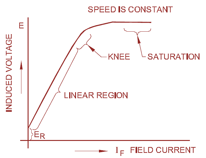
Fig. 3: Separately Excited DC Generator Characteristics
A study of the curve (see Fig. 3) indicates that it starts just above the origin, travels straight in the linear region indicating that the emf induced is directly proportional to the field current IF.
As the poles are in the process of saturation, the relation between the terminal voltage and the field current no longer stands in direct proportion as indicated by the knee portion of the curve.
Finally when the poles get fully saturated the induced emf ceases to increase even at the increased field current which is indicated by the last portion of the curve and named as saturation region.
Load characteristic of a Separately Excited DC Generator:
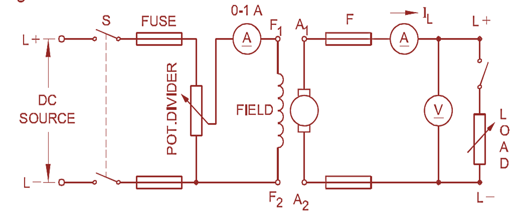
Fig. 4: Separately Excited DC Generator Load characteristic Circuit diagram
The load characteristic shows the relation between the load current and the terminal voltage. Through this characteristic curve, we can determine the behaviour of the generator on load. Fig 4 shows the method of connecting the separately excited DC generator to obtain the load characteristic. The generator speed should be brought to the rated value with the help of the prime mover and the voltage is built up to its normal rated voltage. Then the load switch is closed.
Gradually the load is increased in steps. Each time, the load current IL in amps and the corresponding terminal voltage `V in volts are noted.
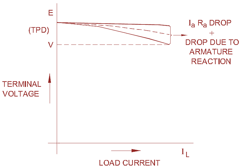
Fig. 5: Separately Excited DC Generator Load characteristic
The graph shown in Fig 5 is the load characteristic or external characteristic of a separately excited generator having load current on the X axis and terminal voltage on the Y axis.
It is observed from the graph that a slight voltage drop occurs when the generator is loaded. This is due to the armature voltage drop (IaRa) and armature reaction. If the voltage drop from no load to full load is very small, the separately excited DC generator can be regarded as a constant voltage generator.
Advantages of a Separately Excited DC Generator
- The terminal voltage remains almost stable when compared to the self-excited generators because the field circuit is independent of the induced voltage.
- As the field is independent, the IaRa drop in the armature will not affect the field flux.
- This generator can be used where a wide range of terminal voltage is required.
Disadvantages of Separately Excited DC Generator
- The inconvenience of providing a separate DC source for excitation.
- Besides it is expensive