A Reflex Klystron is a type of vacuum tube used to generate and amplify microwave signals. It operates on the principle of velocity modulation of an electron beam. Reflex Klystrons are widely used in radar systems, microwave communication, and signal generation due to their simplicity, compactness, and efficiency in producing high-frequency oscillations.

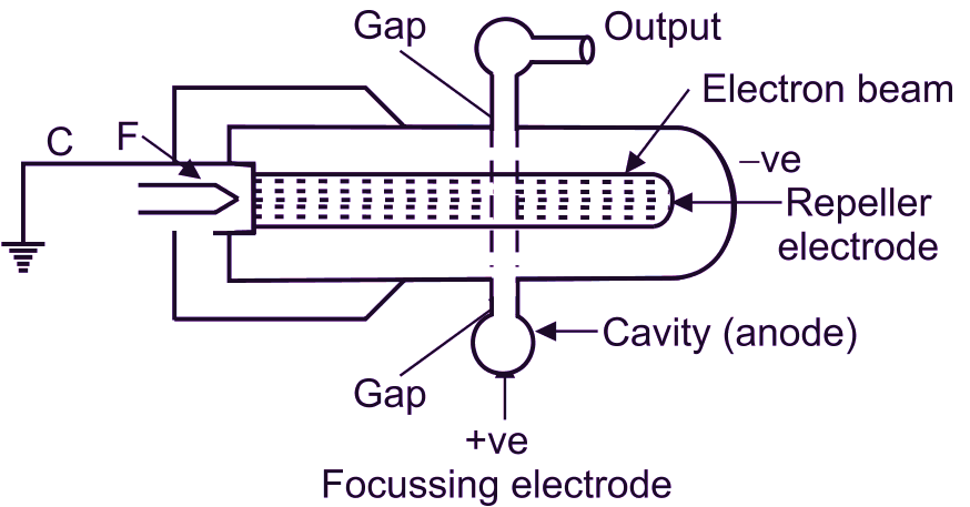
Figure 1: Reflex Klystron.
Parts of a Reflex Klystron
- Cathode: The source of electrons, heated to emit electrons via thermionic emission.
- Focusing Electrode: Shapes and directs the electron beam into a narrow, focused path.
- Cavity Resonator: A metallic structure where the RF field is maintained. It determines the oscillation frequency.
- Repeller Electrode: A negatively charged electrode that reflects electrons back toward the cavity resonator.
- Output Coupling: Extracts the RF signal from the cavity resonator for further use.
- Vacuum Envelope: Encloses the entire assembly, maintaining a vacuum to allow free electron movement.
Diagram of Reflex Klystron
The figure 1 represents a reflex klystron. Key components like the cavity resonator, electron beam path, repeller electrode, and focusing electrode are clearly labeled. The interaction of the electron beam with the cavity and the reflection by the repeller electrode are the central features.
Construction of Reflex Klystron
- Housing: Made of metal or ceramic to provide a sturdy enclosure and maintain a vacuum.
- Electron Gun Assembly: Includes the cathode and focusing electrode for generating and directing the electron beam.
- Resonant Cavity: Designed to resonate at the desired frequency, constructed from high-conductivity materials.
- Repeller System: Positioned beyond the cavity, adjusted to provide the required retarding voltage.
- Cooling System: Prevents overheating of the klystron during operation.
Working of Reflex Klystron
The reflex klystron works on the concept of velocity modulation and electron bunching to generate microwave energy. Here’s a step-by-step explanation:
1. Electron Emission: Electrons are emitted from the cathode via thermionic emission. The emitted electrons are accelerated by the focusing electrode towards the cavity resonator, forming an electron beam.
2. Velocity Modulation: As the electron beam enters the cavity resonator, it interacts with the RF oscillating electric field present in the resonator gap. Depending on the RF voltage at the time the electrons pass through the gap:
- Accelerated Electrons: Gain velocity (arrive earlier at the repeller electrode).
- Decelerated Electrons: Lose velocity (arrive later at the repeller electrode).
- Unaffected Electrons: Maintain their original velocity (arrive at the expected time).
This variation in velocities of the electrons is referred to as velocity modulation.
3. Reflection by the Repeller: The electrons are reflected back by the repeller electrode, which is negatively charged. The time taken by the electrons to return to the cavity depends on their velocity:
- Faster electrons return sooner.
- Slower electrons return later.
As a result, the electrons form bunches while traveling back toward the cavity.
4. Bunching and Energy Transfer: The bunched electrons re-enter the cavity resonator during a specific phase of the RF field, where they transfer their kinetic energy to sustain the oscillations. Maximum energy transfer occurs when the time taken for electrons to travel to the repeller and back (transit time) is synchronized with the RF oscillations.
5. Output Signal Generation: The energy extracted from the electron beam is converted into an RF signal, which is output through a waveguide or antenna.
Phases of Operation

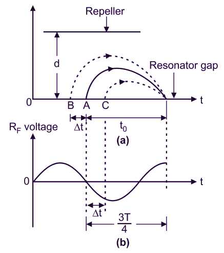
Figure 2.
Figure 2 (a): Electron Trajectories: The electrons (A, B, C) follow different paths due to their varying velocities. Electron A is decelerated, Electron B remains unaffected, and Electron C is accelerated. These electrons form bunches by the time they return to the resonator.
Figure (b): RF Voltage: Shows the sinusoidal variation of RF voltage in the cavity. The phase relation between the RF field and the bunched electrons ensures energy transfer, reinforcing the RF oscillations.
Types of Reflex Klystrons
Reflex klystrons are classified based on their frequency range and power output:
- Low-Power Reflex Klystrons: Used for signal generation in laboratory applications.
- High-Power Reflex Klystrons: Designed for radar systems and communication transmitters.
Applications of Reflex Klystrons
- Microwave Signal Generation: Used in test equipment and signal generators for calibration and research.
- Radar Systems: Essential for short-range radar systems to generate pulsed signals.
- Microwave Communication: Employed in microwave relay links and satellite communication.
- Industrial Heating: Generates high-frequency oscillations for heating and drying applications.
- Medical Equipment: Used in devices like microwave therapy equipment.
Advantages of Reflex Klystron
- Compact and lightweight design.
- Capable of generating high-frequency signals.
- Stable and reliable operation.
- Low cost and easy to manufacture.
Limitations of Reflex Klystron
- Limited power output compared to other microwave devices.
- Efficiency is lower than multi-cavity klystrons.
- Susceptible to frequency drift due to temperature changes.
Conclusion
The reflex klystron is an essential component in microwave technology, offering a simple yet effective solution for generating high-frequency signals. Despite advancements in solid-state devices, reflex klystrons remain relevant in specialized applications due to their unique capabilities. Understanding its working principle, construction, and applications provides a foundation for exploring modern microwave systems.