Dielectric heating, also known as capacitive heating or radiofrequency (RF) heating, is a process in which non-conductive (dielectric) materials are heated by applying an alternating electric field. This heating occurs due to the molecular polarization of the dielectric material when subjected to a high-frequency AC electric field.
It is widely used in industries such as food processing, textile drying, and material curing, where uniform heating of insulating materials is required.
Working Principle of Dielectric Heating

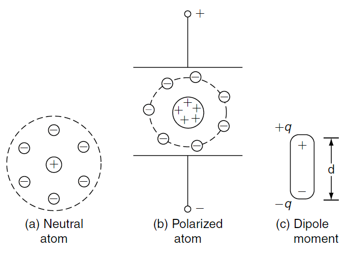
Figure 1: Polarization.
Dielectric heating, also known as capacitive heating, occurs when a non-conductive (dielectric) material is subjected to a high-frequency alternating electric field. This phenomenon involves the following principles:
1. Polarization: In the absence of an external electric field, a neutral atom has a balanced distribution of charges (Fig. 1a). When exposed to an alternating electric field, the positive and negative charges within the dielectric material are displaced, creating polarized atoms (Fig. 1b). This polarization generates a dipole moment (Fig. 1c), which represents the separation of charges and over a distance .
2. High-Frequency Electric Field: A high-frequency alternating voltage is applied across electrodes containing the dielectric material. This results in the continuous realignment of dipoles in the direction of the rapidly changing field.
3. Energy Loss Due to Molecular Friction: The continuous reorientation of dipoles generates friction at the molecular level, leading to heat energy dissipation. This frictional energy loss is called dielectric loss, which is the primary source of heat in dielectric heating.
4. Dielectric Loss and Power Dissipation: The heat generated depends on the loss tangent (), angular frequency \(\omega\), and the applied electric field strength. The power dissipation is given by:
\[
P = V^2 \cdot \omega \cdot C \cdot \tan\delta
\]
where:
\(V\): RMS voltage applied across the dielectric
\(\omega\): Angular frequency of the AC signal (\(\omega = 2\pi f\))
\(C\): Capacitance of the dielectric
\(\tan\delta\): Loss tangent, representing the ratio of resistive power loss to reactive power
5. Heat Distribution: Dielectric heating ensures uniform heating throughout the material as the electric field penetrates uniformly, unlike conventional heating methods where heat is conducted from the surface to the interior.
Working Steps in Dielectric Heating
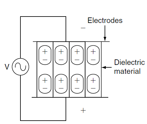
- Application of AC Voltage: An alternating voltage is applied across a dielectric material placed between two electrodes.
- Molecular Polarization: In the presence of an electric field, molecules experience polarization, creating a dipole moment. The electric field continuously reverses its direction due to the alternating nature of the AC signal, causing dipoles to realign.
- Energy Dissipation: The repeated polarization and relaxation of dipoles result in molecular friction, leading to heat generation. This energy dissipation is proportional to the frequency of the AC signal and the dielectric properties of the material.
Circuit Components & Operation in Dielectric Heating

- Electrodes: Conductive plates that create an electric field across the dielectric material.
- Dielectric Material: The insulating substance that undergoes heating.
- AC Voltage Source: Supplies high-frequency alternating current to create the electric field.
The dielectric material is placed between the two electrodes connected to an AC power source. When AC voltage is applied, the electric field alternates at a high frequency. Polarization and depolarization of the dielectric occur as the field oscillates, generating heat within the material.
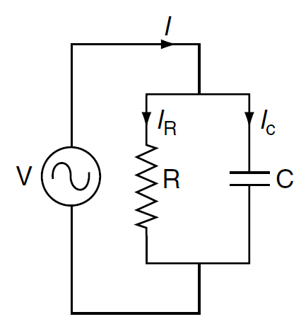
Circuit Diagram & Phasor Diagram of Dielectric Heating

Figure 2: Circuit diagram.

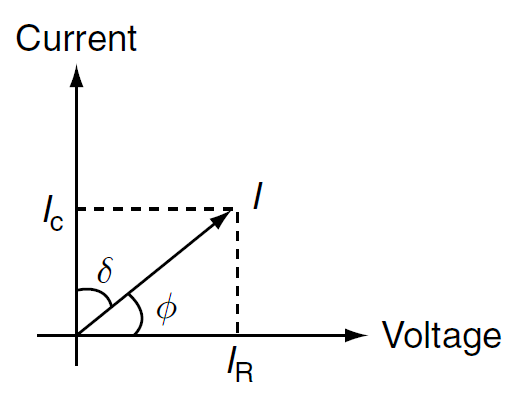
Figure 3: Phasor diagram.
The phasor diagram (see figure 3) illustrates the relationship between voltage, current, and their components in dielectric heating:
- Voltage (V): The applied AC voltage is taken as the reference phasor.
- Current (I): The total current () lags the voltage by an angle , which depends on the dielectric properties.
- Resistive Component ( \( I_R \)): In phase with the voltage and responsible for heat generation.
- Capacitive Component ( \( I_C \)): Leads the voltage by 90°, representing the reactive power in the circuit.
- Loss Angle (): The small angle between the current ( \( I )\) and its capacitive component ( \( I_C )\).
Phasor Relations:
The following phasor relations are used in dielectric heating:
1. Total Current (\(I\))
The total current \(I\) is the vector sum of the resistive current \(I_R\) and the capacitive current \(I_C\):
\[
I = \sqrt{I_R^2 + I_C^2}
\]
2. Resistive Current (\(I_R\))
The resistive current \(I_R\) is in phase with the applied voltage \(V\) and is given by:
\[
I_R = \frac{V}{R}
\]
where \(R\) is the equivalent resistance of the dielectric.
3. Capacitive Current (\(I_C\))
The capacitive current \(I_C\) leads the applied voltage \(V\) by 90° and is expressed as:
\[
I_C = \omega C V
\]
where:
\(\omega = 2\pi f\): Angular frequency of the applied voltage.
\(C\): Capacitance of the dielectric.
\(V\): RMS voltage across the dielectric.
4. Phase Angle (\(\phi\)) Between \(I\) and \(V\)
The phase angle \(\phi\) is the angle between the total current \(I\) and the applied voltage \(V\). It is related to \(I_R\) and \(I_C\) as:
\[
\cos\phi = \frac{I_R}{I}
\]
\[
\tan\phi = \frac{I_C}{I_R}
\]
5. Dielectric Loss Angle (\(\delta\))
The dielectric loss angle \(\delta\) represents the phase difference between the resistive and capacitive currents. It is related to the loss tangent (\(\tan\delta\)) as:
\[
\tan\delta = \frac{I_R}{I_C}
\]
6. Final Relation Between \(\phi\) and \(\delta\)
The phase angle \(\phi\) and the loss angle \(\delta\) are related as:
\[
\phi = 90^\circ – \delta
\]
Derivation of Power Dissipation in Dielectric Heating
The power dissipation (\(P\)) in a dielectric material is derived as follows:
Step 1: Capacitance of the Dielectric Material
The capacitance (\(C\)) of the dielectric material is given by:
\[
C = \frac{\varepsilon \cdot A}{d}
\]
where:
\(\varepsilon\): Permittivity of the dielectric material
\(A\): Area of the electrodes
\(d\): Distance between the electrodes
Step 2: Power Dissipation Formula
The power dissipated in the dielectric material due to the applied voltage \(V\) and the dielectric loss factor is:
\[
P = V^2 \cdot \omega \cdot C \cdot \tan\delta
\]
where:
\(V\): RMS voltage applied across the dielectric
\(\omega\): Angular frequency of the AC signal (\(\omega = 2\pi f\))
\(C\): Capacitance of the dielectric
\(\tan\delta\): Loss tangent, representing the ratio of resistive power loss to reactive power
Step 3: Substitution of Capacitance
Substitute \(C = \frac{\varepsilon \cdot A}{d}\) into the power formula:
\[
P = V^2 \cdot \omega \cdot \frac{\varepsilon \cdot A}{d} \cdot \tan\delta
\]
Final Expression
The final expression for the power dissipation in dielectric heating is:
\[
P = V^2 \cdot \varepsilon \cdot \frac{A}{d} \cdot \omega \cdot \tan\delta
\]
Conclusion
The power dissipation (\(P\)) depends on:
The applied voltage (\(V\))
The frequency of the AC signal (\(f\)) The material properties (\(\varepsilon\) and \(\tan\delta\))
The geometry of the electrodes (\(A\) and \(d\))
Advantages of Dielectric Heating
- Uniform Heating: Ideal for materials with poor thermal conductivity.
- Non-Contact Process: No direct heating elements, reducing contamination risk.
- Selective Heating: Only dielectric materials are heated, leaving other components unaffected.
- Efficiency: High-frequency heating reduces processing time.
- Versatility: Applicable to a wide range of insulating materials.
Disadvantages of Dielectric Heating
- High Initial Cost: Equipment for dielectric heating can be expensive.
- Frequency Sensitivity: The process is effective only at specific frequencies.
- Material Limitation: Only suitable for materials with high dielectric loss factors.
- Energy Loss: High-frequency fields may result in energy dissipation in unintended areas.
Applications of Dielectric Heating
- Food Processing: Pasteurization and drying of food products. Baking and roasting without direct contact with heating elements.
- Textile Industry: Drying of fabrics and yarns. Removing moisture from synthetic materials.
- Plastic and Rubber Curing: Vulcanization of rubber. Preheating thermosetting plastics before molding.
- Wood Processing: Drying and bonding of wood in furniture manufacturing.
- Medical Applications: Sterilization of medical equipment.
Difference Between Induction Heating and Dielectric Heating
| Feature | Induction Heating | Dielectric Heating |
|---|---|---|
| Heating Mechanism | Uses electromagnetic induction to produce eddy currents in a conductive material. | Uses dielectric losses in a non-conductive material under an alternating electric field. |
| Material Type | Applicable to conductive materials like metals. | Applicable to non-conductive or insulating materials. |
| Frequency Range | Typically operates in the range of 1 kHz to 1 MHz. | Typically operates in the range of 10 MHz to 100 MHz. |
| Applications | Used for metal hardening, melting, welding, and forging. | Used for drying wood, heating plastics, and food processing. |
| Efficiency | High efficiency for conductive materials. | Efficient for insulating materials. |
| Temperature Control | Relatively easy to control the temperature. | More challenging to control due to dielectric properties. |
Conclusion
Dielectric heating is a highly efficient and specialized heating technique for insulating materials. Its ability to provide uniform heating with minimal contamination makes it indispensable in industries like food processing, textiles, and material curing. By understanding the principles, circuit operations, and phasor relationships, engineers can optimize dielectric heating systems for various applications.