The Open Circuit and Short Circuit Test on Transformer can be used to determine the efficiency and regulation of a transformer at any predetermined load for that we do not have to actually load the transformer. The parameters of the equivalent circuit of a transformer can be obtained by using the open circuit (O.C.) test and the short circuit (S.C.) test on the transformer.
Open Circuit (O.C.) Test on Transformer
Set-up:

Fig. 1 : Set-up for Open Circuit Test on Transformer.
This test is performed so as to calculate the no load losses (core losses) of a transformer and the values of I0, R0 and X0 of the equivalent circuit. The set up for O.C. test of a transformer is shown in Fig. 1. The primary or secondary winding of the transformer is connected to the rated ac voltage by means of using a variac. The other winding is left open. Generally the high voltage winding is open circuited, and the voltage is applied to the low voltage winding. Assume that this is a step up transformer. A voltmeter is connected across the primary winding to measure the primary voltage. An ammeter is used for measuring the no load primary current (I0) and the wattmeter is connected to measure the input power. The secondary is open circuited because it is an open circuit (O.C.) test. Sometimes a voltmeter is connected across the secondary to measure V2 = E2. Note that the ac supply voltage is applied generally to the low voltage side and the higher voltage side is used as secondary.
Procedure:
- Connect the circuit as shown in Fig. 1.
- Keep the variac at its minimum voltage position.
- Switch on the ac power supply and adjust the variac to get the rated primary voltage as measured by voltmeter V across the primary.
- Now measure the primary current (I0) and power (W0) using the ammeter and wattmeter respectively.
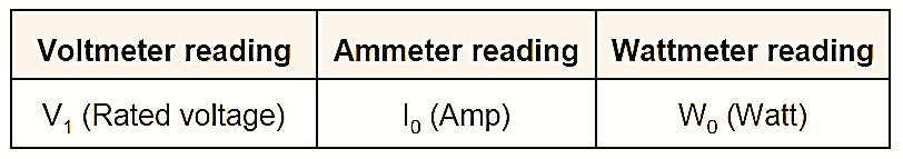
- The ammeter reads the no load primary current I0 whereas the wattmeter measures the no load input power W0.
- The observation table for the O.C. test is as follows.
- The two components of no load current I0 are,
\[{{I}_{m}}={{I}_{0}}\sin {{\phi }_{0}}\]
\[{{I}_{c}}={{I}_{0}}\sin {{\phi }_{0}}\]
- The no load power factor is given by cosϕ0 and the input power at no load is given by,
\[{{W}_{0}}={{V}_{1}}{{I}_{0}}\cos {{\phi }_{0}}\]
- The phasor diagram on no load showing the two components of I0 is shown in Fig. 2.
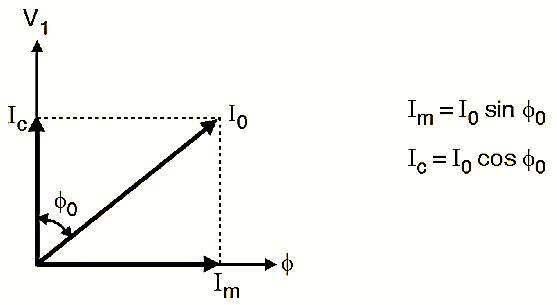
Fig. 2 : Phasor Diagram for Open Circuit Test on Transformer.
- The no load current I0 is very small as compared to the full load primary current. The no load current I0 is about 3 to 5 % of the full load value.
- As I2 is zero, the secondary copper loss is zero. The primary copper loss will be negligible because I0 is small.
- Therefore the total copper loss is very small and can be assumed to be equal to zero. Hence the wattmeter reading W0 represents the iron losses.
\[{{W}_{0}}={{P}_{i}}=\text{ Iron losses}\]
Calculation of parameters:
The two parameters which can be calculated from the open circuit test are R0 and X0. They are calculated as follows.
Step 1: Calculate no load power factor cosϕ0,
The wattmeter reads the real input power.
\[{{W}_{0}}={{V}_{1}}{{I}_{0}}\cos {{\phi }_{0}}\]
And
\[\cos {{\phi }_{0}}=\frac{{{W}_{0}}}{{{V}_{1}}{{I}_{0}}}\]
Calculate ϕ0 from this.
Step 2: Calculate Im and Ic,
\[{{I}_{m}}={{I}_{0}}\sin {{\phi }_{0}}\]
\[{{I}_{c}}={{I}_{0}}\cos {{\phi }_{0}}\]
So calculate Im and Ic from the above equations.
Step 3: Calculate R0 and X0,
\[{{R}_{0}}=\frac{{{V}_{1}}}{{{I}_{c}}}\Omega \]
\[{{X}_{0}}=\frac{{{V}_{1}}}{{{I}_{m}}}\Omega \]
The value of cosϕ0 is very small. Therefore it is necessary to use the low power factor type wattmeter to avoid any possibility of error in measurements.
Short Circuit (S.C.) Test on Transformer
Set-up:
![]()
Fig. 3 : Set-up for short Circuit Test on Transformer.
The set up for carrying out the shown circuit (SC) test on a transformer is shown in Fig. 3. Generally the high voltage side is connected to the ac supply and the low voltage high current side is shorted. Variac is used to adjust the input voltage precisely to the rated voltage. We assume that the transformer used here is a step down transformer. Hence the secondary is shorted and primary is connected to the variac. The voltmeter is connected to measure the primary voltage The ammeter measure the short circuit rated primary current Isc and the wattmeter measures the short circuit input power. The secondary is short circuited with the help of thick copper
Procedure:
- Connect the circuit as shown in Fig. 3.
- Shown circuit the secondary which is a low voltage high current, low resistance winding.
- Keep the variac at its minimum voltage position and switch on the ac supply voltage.
- Increase the primary voltage very gradually: and adjust it to get the primary current equal to the rated value Isc. Do not increase the primary voltage further.
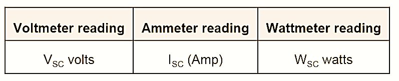
- Note down the wattmeter, voltmeter and ammeter readings. The observation table is as shown below in Table.
Parameter calculations:
The primary and secondary currents are the rated currents. Therefore the total copper loss is the full load copper loss. If we adjust the primary current to half the full load current then we get the copper loss at half load. The iron losses are a function of applied voltage. As the applied voltage in S.C. test is small, the iron losses will be negligibly small. Hence the wattmeter reading Wsc corresponds almost entirely to the full load copper loss.
\[{{W}_{SC}}=\text{ Full load copper loss}\]
\[={{P}_{cu(FL)}}\]
We can calculate the parameters RIT, XIT and ZIT of the equivalent circuit from the short circuit (S.C.) test.
We know that
\[{{W}_{SC}}={{\text{V}}_{SC}}{{I}_{SC}}\cos {{\phi }_{SC}}\]
Hence the short circuit power factor is given by,
\[\cos {{\phi }_{SC}}=\frac{{{W}_{SC}}}{{{V}_{SC}}{{I}_{SC}}}\]
But the wattmeter reading Wsc indicates the full load copper loss.
\[{{W}_{SC}}=\text{Copper loss}\] \[=I_{SC}^{2}\times {{R}_{1T}}\]
\[{{R}_{1T}}=\frac{{{W}_{SC}}}{I_{SC}^{2}}\]
Similarly,
\[{{Z}_{1T}}=\frac{{{V}_{SC}}}{I_{SC}^{{}}}=\sqrt{R_{1T}^{2}+X_{1T}^{2}}\]
\[{{X}_{1T}}=\sqrt{Z_{1T}^{2}+R_{1T}^{2}}\]
In this way the parameters RIT, XIT and ZIT can be calculated from the S.C. test. If the transformation ratio K, it is possible to obtain the parameters referred to the secondary side.
Efficiency Calculation from O.C. and S.C. Test:
The expression for full load efficiency IS given by,
\[{{\eta }_{FL}}=\frac{{{V}_{2}}{{I}_{2(FL)}}\cos \phi }{{{V}_{2}}{{I}_{2(FL)}}\cos \phi +{{P}_{i}}+{{P}_{cu(FL)}}}\]
The iron loss Pi can be obtained from the O.C. test because,
\[ {{W}_{0}}={{P}_{i}}=\text{ Total iron loss}\],
And the full load copper loss is obtained from the S.C. test because,
\[{{\text{W}}_{SC}}={{P}_{cu(FL)}}=\text{ Copper loss}\]
Voltage Regulation Calculation from O.C. and S.C. Test:
The percentage regulation (%R) is given by,
\[\%R=\frac{{{I}_{2}}{{R}_{2T}}\cos \phi \pm {{I}_{2}}{{X}_{2T}}\sin \phi }{{{V}_{2}}}\times 100\]
\[\%R=\frac{{{I}_{1}}{{R}_{1T}}\cos \phi \pm {{I}_{1}}{{X}_{1T}}\sin \phi }{{{V}_{1}}}\times 100\]
We can obtain the parameters such as RIT, XIT, R2T, X2T from the S.C. test of the transformer. Whereas the rated voltages V1,V2 and the rated currents I1 and I2 in the above expressions are known from the given transformer