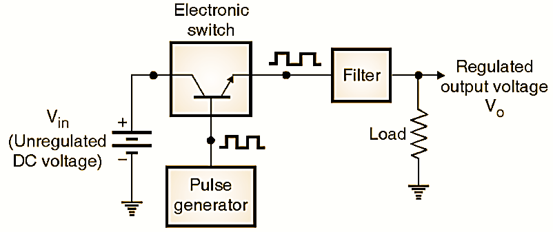
Figure 1: Basic of Switch Mode Power supply (SMPS).
A switch mode power supply (SMPS) is a dc-to-dc series regulated power supply, in which the series pass transistor is operated as a switch. The output voltage of a SMPS is regulated by varying its duty cycle.
In SMPS, the series pass transistor (electronic switch in Fig. 1) does not operate in its active region. Instead it operates as a switch. This is how it is different from the conventional or linear power supply.
Block diagram of Switch Mode Power supply (SMPS)
The block diagram of a basic switching regulator is shown in Fig. 1. The block diagram shows that the SMPS is also a series regulator. The basic switch mode power supply consists of four components namely the unregulated dc voltage source Vin, an electronic switch S (a transistor or MOSFET), a pulse generator and a filter, as shown in Fig. 1.
Working of Switch Mode Power supply (SMPS)
The pulse generator generates rectangular pulses which are applied to the control terminal of an electronic switch. This switch is turned on and off with the help of these rectangular pulses. The switch is an electronic switch which is typically a transistor or MOSFET. It is used in its saturation and cut off regions and not in the active region. When the switch is on, it connects the unregulated dc input Vin as it is to the input of the filter and the filter input is disconnected from the dc input voltage Vin when the switch is open circuited.
Filter input voltage = Vin …..when switch is on
And, filter input voltage = 0 …..when switch is off

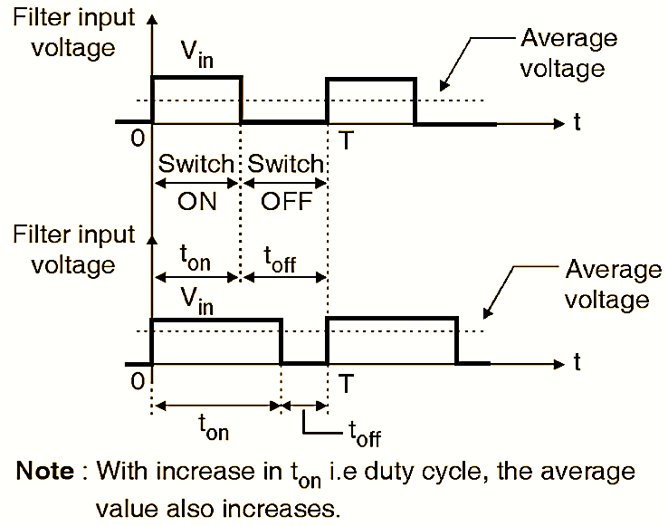
Figure 2: Waveforms of basic Switch Mode Power supply (SMPS).
This is shown in the waveforms of Fig. 2. Therefore at the input of the filter we get a rectangular waveform. The average value of this waveform can be adjusted by changing either the duty cycle or frequency of the rectangular pulses produced by the pulse generator. The duty cycle is defined as,
\[\text{Duty cycle (D) = }\frac{{{t}_{on}}}{{{t}_{on}}+{{t}_{off}}}=\frac{{{t}_{on}}}{T}\]
\[T={{t}_{on}}+{{t}_{off}}=\frac{1}{\text{Frequency}}\]
\[or\text{ T = }\frac{\text{1}}{f}\]
Typically, the operating frequency of the switching regulator will be in the range of 10 to 50 kHz. That means the total time T is of the order of 100 µs to 20 µs. The filter then converts the rectangular waveform at its input into a smooth dc voltage by removing the ripple contents. The expression for dc output voltage of a switching regulator is given by:
\[{{V}_{o}}=\frac{{{t}_{on}}}{T}\times {{V}_{in}}\]
\[or\text{ }{{V}_{o}}=D\times {{V}_{in}}\]
Thus the average output voltage is dependent on the duty cycle D. The average output voltage will increase with increase in the value of duty cycle as shown in Fig. 2.
Advantages of Switch Mode Power supply (SMPS)
The advantages of SMPS are as follows :
- Low power dissipation in the series pass transistor as it operates as a switch and not in the active region.
- High efficiency (upto 95%) due to reduced power dissipation in the transistor.
- Small size : This is due to the smaller size of L and C at high operating frequencies and need of smaller heat sink for the series pass transistor.
- Higher power handling capacity.
Disadvantages of Switch Mode Power supply (SMPS)
The disadvantages of SMPS are as follows :
- Increased switching loss in the series pass transistor due to high frequency switching.
- Radio Frequency Interference (RFD to the neighboring electronic circuits.
- There is no isolation between input and output.
- The load requires separate protection circuitry.
- The transient response is slow as compared to the linear power supplies.
- Ripple content in the output is higher than that for a linear power supply.
- Load regulation is poor as compared to the linear regulators.
Difference between Linear regulator and Switch Mode Power Supply (SMPS)
| Parameter | Linear regulator | SMPS |
| Region of operation of the power transistor | Active region | Saturation or cut-off |
| Switching | No switching | Transistor acts as a switch |
| Complexity | Less | High |
| Efficiency | Low (40%) | High (90%) |
| Switching frequency of the power transistor | Very low | Very high (25 kHz) |
| Switching losses | Zero | Very high |
| RFI/EMI | Absent | Very high |
| Component stress | High | Very high |
| Regulation | Excellent | Good |
| Cost | Lowest | Moderate |
| Size / weight | Large / bulky | Small / light weight |
| Power handling capacity | Low | High |
Types of Switch Mode Power supply (SMPS)

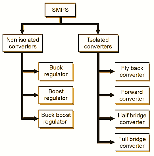
Figure 3: Classification of Switch Mode Power supply (SMPS).
The classification of SMPS is shown in Fig. 3. The SMPS are classified broadly into two categories namely :
- Non-isolated type and
- Isolated type.
No electrical isolation is provided between the load and source in the non-isolated type SMPS. Whereas, a transformer is included for providing the electrical isolation in case of the isolated type SMPS.