In Single Phase Half Wave Controlled Rectifiers the load power can be controlled in only one half cycle of the input ac supply.

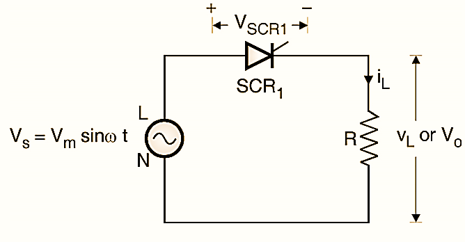
Figure 1: Single Phase Half Wave Controlled Rectifier.
Circuit diagram of Single Phase Half Wave Controlled Rectifier with resistive load
To understand the principle of phase controlled rectifier, refer Fig. 1. It is a half-wave controlled rectifier (HWCR) with a resistive load.
Working of Single Phase Half Wave Controlled Rectifier with resistive load
Operation in the positive half cycle :

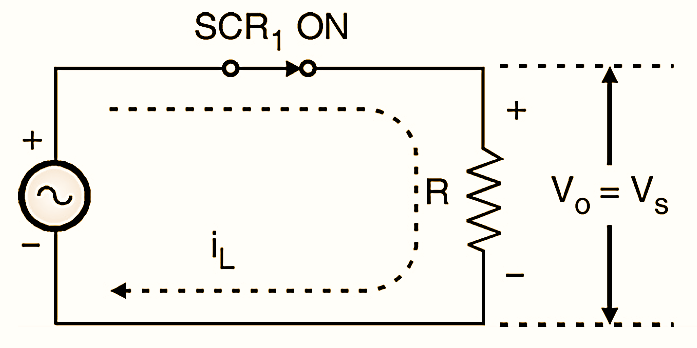
During the positive half cycle of the ac supply, the thyristor SCR1 is forward-biased. When it is turned on at ωt = α the thyristor acts like a closed switch and the input ac voltage appears as it is across the load, as shown in Fig. 2.
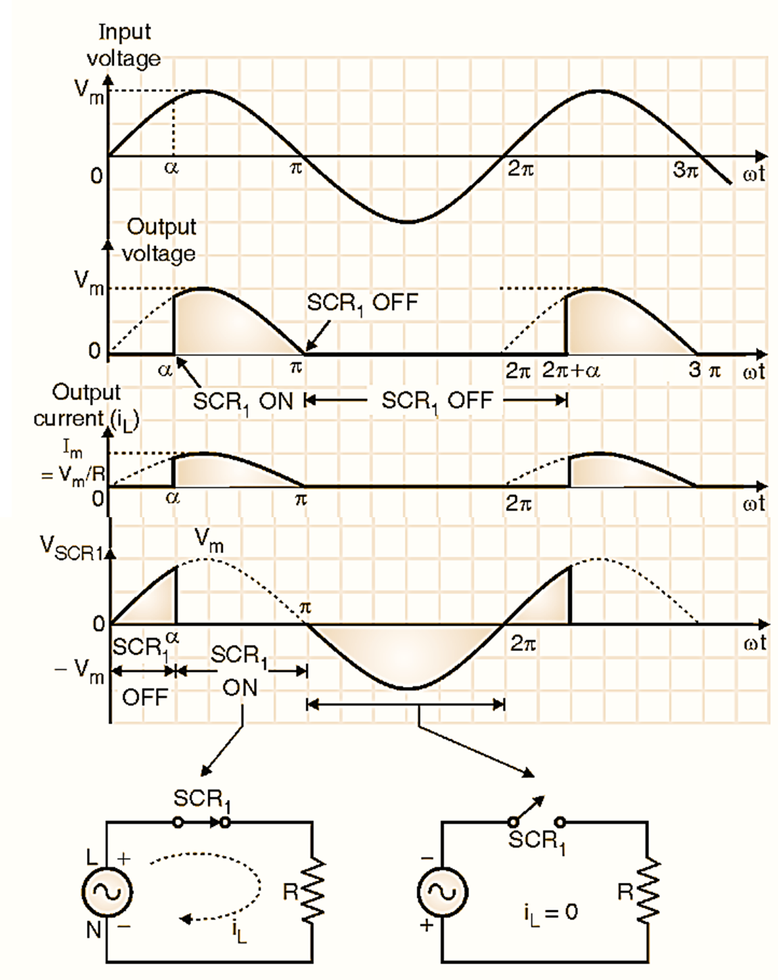
Due to the resistive nature of the load, the load current is in phase with the load voltage. And it has the same shape as that of the load voltage waveform. The instantaneous value of load current is equal to the ratio of instantaneous supply voltage and load resistance R. As the load voltage decreases, the load current also decreases and as this current reduces below the holding current of SCR1, it is commutated due to natural commutation (at ωt = π).
Operation in the negative half cycle :

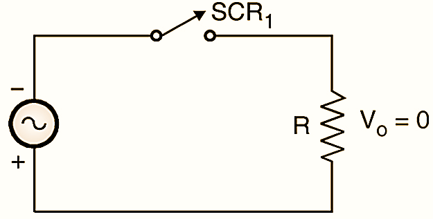
Figure 3: Equivalent circuit in the negative half cycle.
In the negative half cycle, the thyristor is reverse-biased, and acts like an open switch as shown in Fig. 3. The load is disconnected from the input and hence the load voltage is zero. The entire input voltage then appears across the turned-off SCR as shown in Fig. 4. The voltage across the SCR is almost equal to zero when it is in the on state. (α ≤ ωt ≤ π).
Waveforms of Single Phase Half Wave Controlled Rectifier with resistive load

Figure 4: Waveforms of Single Phase Half Wave Controlled Rectifier.
The voltage and current waveforms for the HWCR with resistive load are as shown in Fig. 4.
Average output voltage (VLdc):
From the load voltage waveform in Fig. 2 the average output voltage VLdc can be found as follows :
\[{{V}_{LDC}}=\frac{1}{2\pi }\int\limits_{\alpha }^{\pi }{{{V}_{m}}\sin \omega t\text{ }d\omega \text{t}}\]
\[=\frac{-{{V}_{m}}}{2\pi }\left[ \cos \omega t \right]_{\alpha }^{\pi }\]
\[=\frac{{{V}_{m}}}{2\pi }(1+\cos \alpha )….(1)\]
Equation (1) shows that the average load voltage VLdc can be varied from 0 to Vm/π by varying α between π to 0 radians respectively. The average voltage will be maximum when u and it is given by,
\[{{V}_{\text{LDC(max)}}}=\frac{{{V}_{m}}}{2\pi }(1+\cos 0)\]
\[=\frac{{{V}_{m}}}{\pi }\]
Concept of phase control:
Equation (1) shows that the average load voltage VLdc can be varied from 0 to (Vm/π) by varying α between π to 0 radians respectively. The average voltage will be maximum when α = 0 and it is given by,
\[{{V}_{\text{LDC(max)}}}=\frac{{{V}_{m}}}{2\pi }(1+\cos 0)=\frac{{{V}_{m}}}{\pi }\]
Thus it is possible to control the average load voltage and hence average load power by controlling the firing angle and phase angle α of the controlled rectifier. This is the basic concept of phase control.
Drawbacks of Single Phase Half Wave Controlled Rectifier with resistive load
- The output voltage contains large ripple and the ripple frequency is low (50 Hz). This will make the filter design difficult and the filter becomes bulky.
- The average output voltage \({{V}_{\text{LDC}}}=\frac{{{V}_{m}}}{2\pi }(1+\cos \alpha )\) is low due to half wave rectification and will not be useful in most of the applications.
- The supply current is distorted and contains harmonic currents.
- In addition to that the supply current contains dc component.
- The input power factor is very poor.