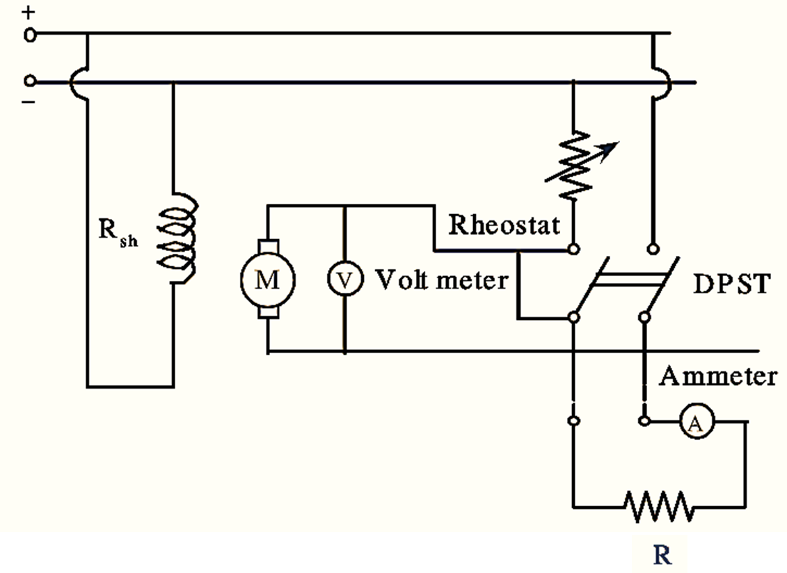
Retardation Test is used for finding the efficiency of shunt wound DC machines. In this test, the rotational losses or stray losses are measured and from their knowledge efficiency at any desired load can be determined.

Figure 1: Arrangement of Retardation Test.
In this method of testing DC machines, the machine runs slightly above its normal speed and supply to the armature is cut-off while the field remains excited. As a result, the armature slows down and its kinetic energy is utilized to overcome rotational losses.
\[\text{K}\text{.E}\text{. of armature = }\frac{1}{2}I{{\omega }^{2}}\]
Where,
I = M.I (i.e., moment of inertia) of armature
ω = Angular speed of armature
PR = Rate of change of K.E.
\[=\frac{d}{dt}\left( \frac{1}{2}I{{\omega }^{2}} \right)=I\omega \frac{d\omega }{dt}\]
\[=I\left( \frac{2\pi N}{60} \right)\frac{d}{dt}\left( \frac{2\pi N}{60} \right)\]
\[={{\left( \frac{2\pi }{60} \right)}^{2}}IN\frac{dN}{dt}….(1)\]
Hence to determine stray losses, the value of M.I of armature i.e., I and rate of change of speed i.e., \(\frac{dN}{dt}\) must be known. Determination of \(\frac{dN}{dt}\).
The connections for conducting retardation test are shown in figure. The voltmeter V across armature shows the instantaneous back e.m.f. Since Eb ∝ N, the voltmeter can be suitably calibrated to indicate speed. When the supply to armature is cut off the speed of machine decreases with time. The speed or readings of voltmeter are noted at different intervals of time and a curve is drawn between speed and time.
From any point, ‘P’ lying on speed time curve, tangent is drawn meeting the X-axis and Y-axis at A and B respectively. Then,
\[\frac{dN}{dt}=\frac{\text{OB in r}\text{.p}\text{.m}}{\text{OA }\text{in sec}}\]
Determination of M.I (Moment of Inertia) :
First speed time curve is plotted with armature alone. Then a flywheel of known M.I i.e., I1 is keyed to the shaft and speed time curve is plotted again.
Due to the addition of flywheel, the time taken to lower the speed will be longer. \(\frac{dN}{d{{t}_{1}}}\) and \(\frac{dN}{d{{t}_{2}}}\) will be determined as before, losses will remain the same in both cases since the addition of flywheel will not make much difference.
Rotational losses before the addition of flywheel,
\[{{\left( \frac{2\pi }{60} \right)}^{2}}IN\frac{dN}{d{{t}_{1}}}….(2)\]
Rotational losses after the addition of flywheel,
\[{{\left( \frac{2\pi }{60} \right)}^{2}}(I+{{I}_{1}})N\frac{dN}{d{{t}_{2}}}….(3)\]
Equating equation (2) and (3), we get,
\[{{\left( \frac{2\pi }{60} \right)}^{2}}(I+{{I}_{1}})N\frac{dN}{d{{t}_{2}}}={{\left( \frac{2\pi }{60} \right)}^{2}}IN\frac{dN}{d{{t}_{1}}}\]
\[=I\left( \frac{dN}{d{{t}_{1}}}-\frac{dN}{d{{t}_{2}}} \right)={{I}_{1}}\frac{dN}{d{{t}_{2}}}\]
\[I=\frac{{{I}_{1}}\left( \frac{dN}{d{{t}_{2}}} \right)}{\frac{dN}{d{{t}_{1}}}-\frac{dN}{d{{t}_{2}}}}\]
Substituting the values of I1,
\(\frac{dN}{d{{t}_{1}}}\) and \(\frac{dN}{d{{t}_{2}}}\) in above equation the value of I can be determined using retardation test.