A 765 kV transmission line is an extra-high-voltage (EHV) overhead power transmission system used to transfer huge amounts of electrical power over very long distances with minimal losses. It is one of the highest voltage levels used in AC power transmission and plays a vital role in modern national and inter-regional power grids.
Key Point:
What is a 765 kV Transmission Line?
A 765 kilovolt (kV) transmission line is an overhead AC transmission line designed to operate at a line-to-line voltage of 765,000 volts. These lines are classified under Extra High Voltage (EHV) transmission systems and are primarily used for bulk power transmission from generating stations to major substations.
Due to the extremely high voltage, 765 kV lines require special tower designs, long insulator strings, bundled conductors, and large right-of-way clearance.
Need for 765 kV Transmission Lines
As electricity demand increases, transmitting power at lower voltages becomes inefficient due to higher losses and voltage drops. The 765 kV system was introduced to:
- Transmit bulk power over long distances
- Reduce transmission losses
- Improve grid stability
- Minimize number of transmission corridors
- Support large thermal, hydro, and nuclear power plants
Construction of 765 kV Transmission Line
The construction of a 765 kV transmission line is much more robust and complex than lower voltage lines. Each component is specially designed to withstand high electrical, mechanical, and environmental stresses.
Main Components
1. Transmission Towers
Steel lattice towers are commonly used. These towers are very tall (45–60 meters) to maintain safe ground clearance and reduce electric field effects.
2. Conductors
765 kV lines use bundled conductors (usually 4 or 6 sub-conductors per phase) made of ACSR (Aluminum Conductor Steel Reinforced) or AAAC.
3. Insulators
Long strings of disc insulators or composite insulators are used to withstand high voltage and prevent flashover.
4. Ground (Shield) Wire
Installed at the top of the tower to protect the line from lightning strikes.
5. Spacers and Dampers
Used to maintain spacing between bundled conductors and reduce vibration.
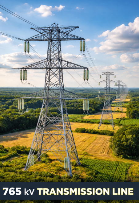
765 kV Transmission Line Diagram
A typical 765 kV transmission line diagram includes:
- Steel lattice tower
- Bundled phase conductors
- Long insulator strings
- Shield wire on top
- Wide phase spacing
(The figure above represents a realistic structure of a 765 kV overhead transmission line.)
Working Principle of 765 kV Transmission Line
The working principle of a 765 kV transmission line is based on high-voltage AC power transmission.
Step-by-Step Working
- Electric power is generated at power plants (typically 11–25 kV).
- The voltage is stepped up to 765 kV using step-up transformers.
- Power flows through 765 kV transmission lines with low current.
- Reduced current minimizes copper losses (I²R losses).
- At receiving substations, voltage is stepped down for distribution.
The use of EHV transmission improves efficiency, reliability, and stability of the power system.
Types of 765 kV Transmission Lines
| Type | Description | Application |
|---|---|---|
| Single Circuit 765 kV Line | One three-phase circuit mounted on towers | Long-distance bulk power transmission |
| Double Circuit 765 kV Line | Two independent 765 kV circuits on same tower | High capacity corridors |
| HVAC 765 kV Line | Alternating current transmission | Most common in power grids |
| Hybrid HVAC-HVDC Corridor | Combination of AC and DC lines | Grid stability improvement |
Advantages of 765 kV Transmission Line
- Very low transmission losses
- High power transfer capability
- Improved voltage regulation
- Reduced number of transmission lines
- Better grid reliability and stability
- Efficient use of right-of-way
- Supports large power plants
Disadvantages of 765 kV Transmission Line
- High initial installation cost
- Large tower size and land requirement
- Complex insulation design
- Corona loss and radio interference
- Maintenance requires skilled manpower
- Visual and environmental impact
Applications of 765 kV Transmission Line
765 kV transmission lines are mainly used in:
- National power grid interconnections
- Transmission from super thermal power plants
- Nuclear and hydro power stations
- Bulk power corridors
- Cross-regional electricity transfer
- Smart grid and super grid projects
Comparison with Lower Voltage Transmission Lines
| Parameter | 400 kV Line | 765 kV Line |
|---|---|---|
| Voltage Level | 400,000 V | 765,000 V |
| Power Capacity | Moderate | Very High |
| Transmission Loss | Higher | Lower |
| Tower Size | Smaller | Larger |
| Cost per km | Lower | Higher |
Conclusion
The 765 kV transmission line is a backbone of modern high-capacity power systems. It enables efficient long-distance transmission of electricity with minimal losses and plays a crucial role in meeting growing energy demands. Although the initial cost is high, its long-term benefits in efficiency, reliability, and grid stability make it indispensable for large-scale power networks.