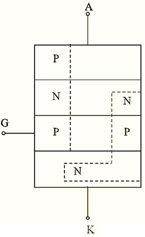
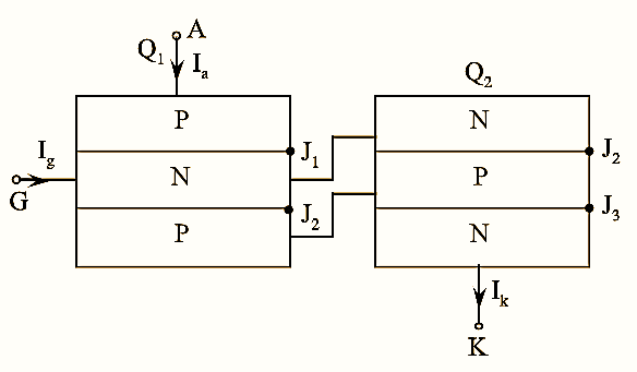
Two-transistor model is used to explain the principle of operation of Silicon Controlled Rectifier (SCR). Since, a SCR is a four layered PNPN device, it can be considered as a combination of two transistors, one transistor as PNP and the other transistor as NPN which are connected back to back.


Figure 1: Structure of Two-transistor model of SCR.

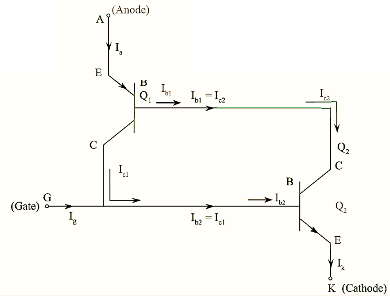
Figure 2: Equivalent Circuit of Two-transistor model of SCR.
Two-transistor model is obtained by separating the two middle layer of SCR as shown in figure (1). The equivalent circuit of two-transistor analogy is shown in figure (2).
From figure (2), we have,
\[{{I}_{b1}}={{I}_{c2}}\]
\[{{I}_{c1}}={{I}_{b2}}\]
Cathode current = Anode current + Gate current
\[{{I}_{k}}={{I}_{a}}+{{I}_{g}}….(1)\]
The basic relation between collector current, Ic and emitter current IE is given as,
\[{{I}_{c}}=\alpha {{I}_{E}}+{{I}_{CBO}}\]
α – Common-base current gain ≅ Ic / IE
ICBO – Leakage current of collector-base.
Hence, in the given equivalent circuit,
\[{{I}_{c1}}={{\alpha }_{1}}{{I}_{E1}}+{{I}_{CBO1}}\]
\[{{I}_{c2}}={{\alpha }_{2}}{{I}_{E2}}+{{I}_{CBO2}}\]
Here,
\[{{I}_{E1}}\text{ of }{{Q}_{1}}={{I}_{a}}\text{ and }{{I}_{E2}}\text{ of }{{Q}_{2}}={{I}_{c}}\]
Substituting the values of IE1, IE2 in equation IC1 and IC2, we get,
\[{{I}_{c1}}={{\alpha }_{1}}{{I}_{a}}+{{I}_{CBO1}}….(2)\]
\[={{\alpha }_{2}}{{I}_{c}}+{{I}_{CBO2}}….(3)\]
The sum of two collector currents is equal to an anode current, i.e.,
\[{{I}_{a}}={{I}_{c1}}+{{I}_{c2}}….(4)\]
Substituting equation (2) and (3) in equation (4), we get,
\[{{I}_{a}}={{\alpha }_{1}}{{I}_{a}}+{{I}_{CBO1}}+{{\alpha }_{2}}{{I}_{c}}+{{I}_{CBO2}}\]
From transistor analysis, we have,
\[{{I}_{e1}}={{I}_{b1}}+{{I}_{c1}}\]
\[{{I}_{e1}}={{I}_{b1}}+{{I}_{c1}}….(5)\]
Substituting equation (1) in equation (4), we get,
\[{{I}_{a}}={{\alpha }_{1}}{{I}_{a}}+{{I}_{CBO1}}+{{\alpha }_{2}}({{I}_{a}}+{{I}_{g}})+{{I}_{CBO2}}\]
\[{{I}_{a}}={{\alpha }_{1}}{{I}_{a}}+{{I}_{CBO1}}+{{\alpha }_{2}}{{I}_{a}}+{{\alpha }_{2}}{{I}_{a}}+{{\alpha }_{2}}{{I}_{g}}+{{I}_{CBO2}}\]
\[{{I}_{a}}={{I}_{a}}({{\alpha }_{1}}+{{\alpha }_{2}})+{{\alpha }_{2}}{{I}_{g}}+{{I}_{CBO1}}+{{I}_{CBO2}}\]
\[{{I}_{a}}(1-({{\alpha }_{1}}+{{\alpha }_{2}}))={{\alpha }_{2}}{{I}_{g}}+{{I}_{CBO1}}+{{I}_{CBO2}}\]
\[{{I}_{a}}=\frac{{{\alpha }_{2}}{{I}_{g}}+{{I}_{CBO1}}+{{I}_{CBO2}}}{1-({{\alpha }_{1}}+{{\alpha }_{2}})}\]
Since, ICBO1 and ICBO2 are very small, ‘Ia‘ can be written as,
\[{{I}_{a}}=\frac{{{\alpha }_{1}}{{I}_{g}}}{1-({{\alpha }_{1}}+{{\alpha }_{2}})}\]
If α1 + α2 = 1 then anode current Ia becomes infinity and hence thyristor enters into conduction state from OFF state.