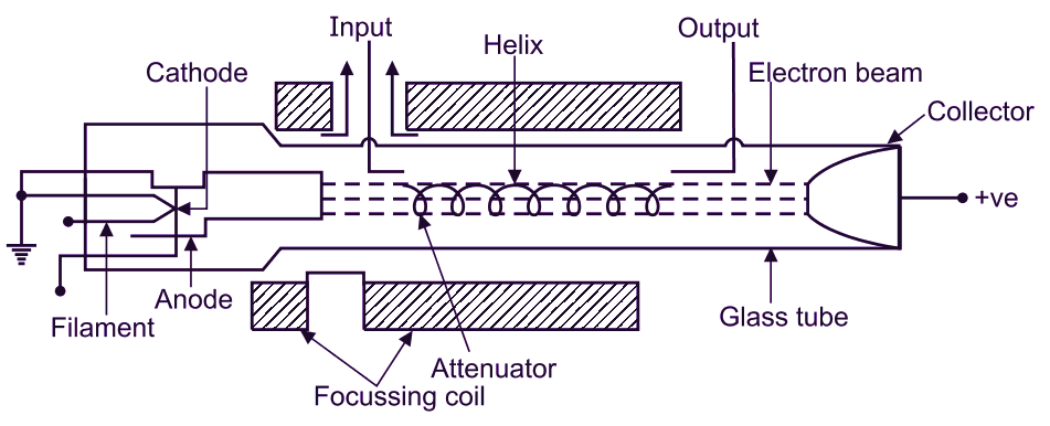
A Travelling Wave Tube (TWT) is a specialized vacuum tube that amplifies microwave signals by interacting with an electron beam traveling through a helical slow-wave structure. It is widely used in radar, satellite communication, and electronic warfare due to its high power and broadband amplification capabilities.
Parts of Travelling Wave Tube (TWT)
The Travelling Wave Tube (TWT) consists of several essential components that facilitate the amplification of microwave signals. Below are the key parts along with their functions:
1. Electron Gun: Composed of filament, cathode, and anode. Generates and accelerates an electron beam. The filament heats the cathode, which emits electrons via thermionic emission. The anode helps focus and accelerate the electrons.
2. Focusing System: Uses focusing coils or permanent magnets to maintain the electron beam’s trajectory. Prevents beam divergence and enhances efficiency.
3. Slow-Wave Structure (Helix): A helical coil that slows down the RF wave to synchronize with the electron beam. Enables effective interaction and energy exchange for amplification.
4. RF Input & Output Couplers
- RF Input Coupler: Introduces the weak microwave signal into the TWT.
- RF Output Coupler: Extracts the amplified microwave signal.
5. Attenuator: A resistive material placed along the helix. Absorbs unwanted reflected waves, preventing oscillations and instability.
6. Collector: A positively charged electrode that collects spent electrons after signal amplification. Some designs use multi-stage collectors to improve efficiency and energy recovery.
7. Vacuum Enclosure (Glass Tube): A sealed vacuum tube that provides an electron-free environment for beam travel. Prevents collisions that could disrupt the electron beam.
These components work together to achieve high-gain, broadband microwave signal amplification, making TWTs essential for satellite communication, radar systems, and electronic warfare.
Working of Travelling Wave Tube (TWT)
The working of a TWT is based on the interaction between a high-velocity electron beam and a slow-wave RF structure (typically a helix). The traveling RF wave causes velocity modulation in the electron beam, leading to the formation of electron bunches. These bunches transfer energy to the RF wave, amplifying it as it propagates through the tube.
Types of Travelling Wave Tube (TWT)
| Type | Description | Advantages | Disadvantages | Applications |
|---|---|---|---|---|
| Helix TWT | Uses a helical wire to slow RF waves, enabling broadband operation. | Wide bandwidth, high gain, low noise. | Lower power efficiency, high heat generation. | Satellite communication, radar, electronic warfare. |
| Coupled-Cavity TWT | Uses a series of resonant cavities instead of a helix for interaction. | Handles high power, efficient energy transfer. | Narrower bandwidth, complex structure. | High-power radar, military jamming systems. |
| Folded Waveguide TWT | Uses a folded waveguide to guide RF energy for amplification. | More compact and durable than helix TWTs. | Moderate power and bandwidth. | High-frequency radar, military applications. |
Construction of Travelling Wave Tube (TWT)
The Helix TWT consists of a long cylindrical vacuum tube with an electron gun at one end, producing a high-speed electron beam. A helical wire surrounds the beam, allowing the RF signal to travel along it. The interaction of the wave with the beam causes energy transfer, leading to amplification. Finally, the spent electron beam is collected at the collector.
Advantages of Travelling Wave Tube (TWT)
- High Gain & Power Output: Provides high amplification with gains of 40–70 dB. Can deliver high power output (from a few watts to kilowatts).
- Broadband Operation: Operates over a wide frequency range (GHz range). Ideal for broadband communication and radar systems.
- High Efficiency: Can achieve efficiencies of 20-40% depending on the design.
- Better Linearity: Less distortion compared to solid-state amplifiers. Suitable for amplifying complex modulated signals (used in satellite communication).
- Low Noise Figure: Generates less internal noise, making it ideal for sensitive communication systems.
- High Frequency & Microwave Operation: Can operate at frequencies up to 50 GHz and beyond. Used in satellites, radars, and electronic warfare.
- Stable & Reliable: Offers long operational life with stable performance. Used in demanding environments such as space and defense applications.
Disadvantages of Travelling Wave Tube (TWT)
- Complex Construction: Requires precise vacuum technology and high-precision machining. Expensive to manufacture.
- High Voltage Requirement: Needs high voltage power supplies (several kV) for operation. Increases complexity and safety concerns.
- Bulky & Heavy: Larger and heavier compared to solid-state power amplifiers (SSPAs). Less suitable for portable applications.
- Limited Lifespan: Electron emission from the cathode degrades over time. Lifespan is shorter compared to solid-state devices.
- Thermal Issues: Generates significant heat due to electron beam interaction. Requires efficient cooling systems.
- Susceptibility to Damage: Can be damaged by shock, vibrations, and high voltage variations. Sensitive to environmental conditions.
Applications of Travelling Wave Tube (TWT)
- Satellite Communication – Used in transponders for signal amplification.
- Radar Systems – Essential for high-power radar transmitters.
- Electronic Warfare – Jamming and countermeasure systems.
- Medical Equipment – Used in high-frequency imaging applications.
