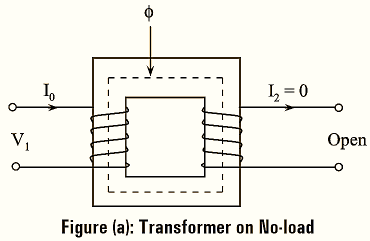
When the transformer is on no-load, the secondary winding is opened as in figure (a) and current I2 is zero. In this condition, the primary winding draws a no-load current ‘I0‘ which has two components i.e.,
- Magnetizing component (Iµ), and
- Working component (Iw).
1. Magnetizing Component (Iµ) :
It lags behind the applied voltage on primary winding ‘V1‘ by 90º. It is also called as reactive or wattless component of no-load current and is responsible to develop an e.m.f to maintain the flux ‘ϕ’ in the core. It is expressed as \({{I}_{\mu }}=\text{ }{{I}_{0}}\sin {{\phi }_{0}}\).
2. Working Component (Iw) :
It is in phase with the primary applied voltage ‘V1‘. The component is also called as active component or iron loss component, and is used for describing the core losses such as hysteresis loss and eddy current loss. It is expressed as \({{I}_{w }}=\text{ }{{I}_{0}}\cos {{\phi }_{0}}\).
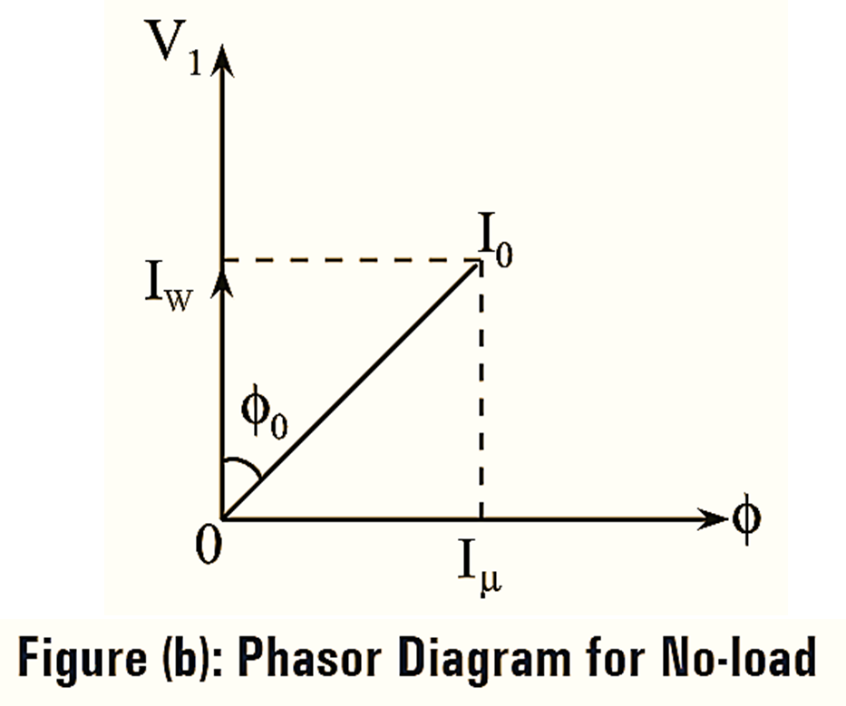
From the phasor diagram of figure (b),
\[\sin {{\phi }_{0}}=\frac{{{I}_{\mu }}}{{{I}_{0}}}\]
Thus, \({{I}_{\mu }}={{I}_{0}}\sin {{\phi }_{0}}\) is the reactive component of no-load current I0 and
\[\cos {{\phi }_{0}}=\frac{{{I}_{w }}}{{{I}_{0}}}\]
Thus, \({{I}_{w }}={{I}_{0}}\cos {{\phi }_{0}}\) is the active component of no load current I0.
Hence,
\[{{I}_{0}}=\sqrt{I_{w}^{2}+I_{\mu }^{2}}\]
cosϕ0 is the no-load power factor and ϕ0 is the hysteresis angle of advance.