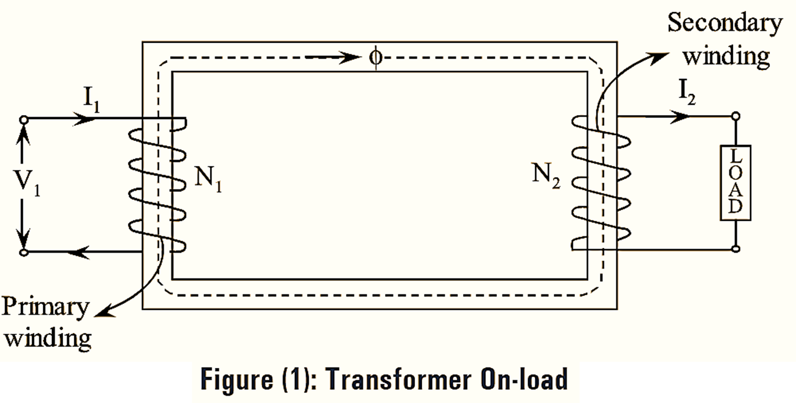
When the transformer is on load, the secondary winding is connected with load as in figure (1) and current I2 is flowing through load.

Operation of Transformer On load
Figure (1) shows a transformer with a load connected across the secondary winding. The load current I2 flowing through the secondary turns sets up its own m.m.f N2I2 which produces the flux ϕ2.
According to Lenz’s law this flux is in such a direction that it opposes the flux ϕ, produced by the m.m.f N1I0 which is set up by the no-load current I0 flowing throw the primary turns. Consequently the flux is momentarily reduced due to opposing flux ϕ. This in turn causes reduction in induced e.m.f (E1) in primary according to Faraday’s law E1 reduces, the difference between applied voltage (V1) and E1 increases.
Consequently, the primary will draw more current. Consider \({{{I}’}_{1}}\) to be this additional primary current. It is also known as counter balancing current as it balances between applied voltage and primary e.m.f or it is known as load component of primary current and it is antiphase with secondary current I2. Now this current \({{{I}’}_{1}}\) sets up its own m.m.f N1\({{{I}’}_{1}}\) which produces the flux and it is equal in magnitude in such a direction that it opposes the flux ϕ2. Hence ϕ’1 and ϕ2 cancel each other and only flux ϕ flows in the core. Therefore the total flux produced during loaded condition is approximately equal to the flux at no-load.
\[{{\phi }_{2}}=-{{{\phi }’}_{1}}\]
As secondary ampere turns of I2 are neutralized by primary ampere turns of \({{{I}’}_{1}}\).
\[{{N}_{2}}{{I}_{2}}={{N}_{1}}{{{I}’}_{1}}\]
\[{{{I}’}_{1}}=\frac{{{N}_{2}}}{{{N}_{1}}}{{I}_{2}}\]
The net primary current is the vector sum of primary counter balancing current \({{{I}’}_{1}}\) and the no-load current I0.
\[{{I}_{1}}={{{I}’}_{1}}+{{I}_{0}}\]
Since the no-load current I0 is very small compared to the counter balancing current \({{{I}’}_{1}}\), therefore the net primary current is approximately equal to the current \({{{I}’}_{1}}\).
\[{{I}_{1}}={{{I}’}_{1}}\]
\[=\frac{{{N}_{2}}}{{{N}_{1}}}{{I}_{2}}=K{{I}_{2}}\]
‘K’ represents transformation ratio.
\[\frac{{{I}_{1}}}{{{I}_{2}}}=\frac{{{{{I}’}}_{1}}}{{{I}_{2}}}=\frac{{{N}_{2}}}{{{N}_{1}}}=K\]
\[{{I}_{1}}=K{{I}_{2}}={{{I}’}_{1}}\]
Therefore, the primary and secondary currents are inversely proportional to their turns ratio. The total primary current is in anti-phase with I2 and K times the current I2.
Phasor Diagram of Transformer with Resistive Load

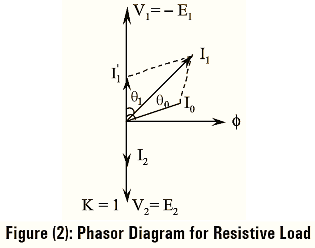
The phasor diagram for resistive load is drawn as shown in the following figure (2). For purely resistive load, the secondary load current I2 is in phase with the secondary’ terminal voltage V2. The counter balancing current \({{{I}’}_{1}}\) is in opposition and equal in magnitude with the secondary load current I2. The primary current I1 is the vector sum of \({{{I}’}_{1}}\) and no-load current I0 respectively. I0 lags behind V1 by no-load power factor angle ϕ0 and I1 lags behind the voltage V1 by primary power factor angle ϕ1.